
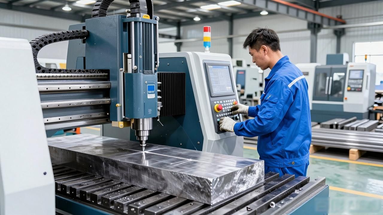
Wire-cut die-cutting process
The die contains a punch, which plays a crucial role; its design, dimensional accuracy and material hardness all have a direct impact on the quality of the die-cutting process, the service life of the die, and the precision of the stamped parts. In actual wire-cut EDM production, the interior of the workpiece blank is subject to deformation caused by residual stresses, compounded by thermal stress deformation resulting from the electrical discharge. It is therefore necessary to machine the wire-passage holes first and carry out closed-loop cutting, whilst avoiding open-loop cutting as far as possible to prevent deformation. If closed-loop cutting is not feasible due to the dimensions of the workpiece blank, care must be taken when programming the cutting path or direction, particularly for square blanks.
During wire cutting, the cutting path must be designed to ensure that the workpiece remains within the same coordinate system as the fixture (clamping support frame) throughout the machining process, thereby avoiding the effects of stress deformation. The fixture is secured at the left-hand end; cutting commences from the left side of the bell-shaped die and proceeds in an anti-clockwise direction. The entire blank is divided into left and right sections along the cutting path. As the material connecting the left and right sides of the blank gradually decreases, the right side of the blank becomes progressively detached from the fixture. Unable to withstand the internal residual stresses, it deforms, causing the workpiece to deform as well. If cutting were to be carried out in a clockwise direction, the workpiece would remain on the left-hand side of the blank, close to the clamping area. For the majority of the cutting process, the workpiece and the fixture would remain within the same coordinate system, ensuring good rigidity, thereby preventing stress-induced deformation. Generally speaking, a reasonable cutting path should place the cutting segment that separates the workpiece from the clamping area at the end of the overall cutting programme; in other words, the pause point should be positioned near the end of the blank where it is clamped.
The following section focuses on an analysis of the cutting process for cemented carbide toothed punches. Under normal circumstances, when the die has a regular shape, wire-cut EDM often leaves a connecting section—known as a ‘pause point’—which is a small segment of the cutting path intentionally retained to ensure that the workpiece does not become completely detached from the blank after the first rough cut; is positioned on a flat surface. After the majority of the finishing cuts have been completed, the reserved connecting section is cut just once, after which a fitter grinds it down to a smooth finish; this approach helps to reduce the machining costs associated with slow-wire EDM of the punch.
Due to their high material hardness and elongated shape, cemented carbide punches result in slow machining speeds and are prone to deformation, particularly when their shape is irregular; the grinding of the reserved connection section presents considerable difficulty for fitters. Therefore, by making appropriate adjustments to the process during the slow-wire EDM machining stage, dimensional accuracy can be achieved, thereby eliminating the need for fitters to grind the stop points prior to assembly.
As cemented carbide is extremely hard and the cutting depth is considerable, this results in a slow machining speed and severe torsional deformation. Consequently, most contour machining operations, as well as the machining of connection sections (pause points), employ a four-pass cutting method, with the cutting parameters and offset () being identical for both sections. During the first pass, the electrode wire offset is increased to 0.5–0.8 mm, thereby allowing the workpiece to fully release internal stresses and undergo complete torsional deformation; this provides sufficient allowance for the subsequent three passes to carry out precision cutting, thus ensuring the final dimensions of the workpiece are maintained.
A detailed analysis of the process is as follows:
(1) Position the blank correctly in advance, and use a wire-piercing machine or an EDM forming machine to machine a wire-passing hole with a diameter of Φ1.0–Φ1.5 mm; The length of the lead-in segment l between the centre of the wire-threading hole and the contour line of the punch should be selected to be between 5 and 10 mm.

(2) The contour of the punch must extend at least one-fifth of the blank’s thickness beyond the edge of the blank.
(3) The connection section reserved for subsequent wire-cut EDM—that is, the breakpoint—should be positioned close to the centre of gravity of the workpiece blank, and its width should be between 3 and 4 mm. That is correct.
(4) In order to compensate for torsional deformation, the majority of the residual deformation is retained during the first rough-cutting stage, and the offset is increased to between 0.5 and 0.8 mm. In the subsequent three passes, using the fine-cutting method, the amount of deformation decreased accordingly, given the smaller cutting allowance in wire-cut EDM.
(5) Once the majority of the outer shape has been machined through four cutting operations, the workpiece is blown dry with compressed air, then the end face of the blank is cleaned with an alcohol solution and left to air-dry, after which a metal sheet approximately 1.5 mm thick, which has been ground flat on a grinding machine, is firmly bonded to the blank using an adhesive or liquid instant adhesive (typically 502 instant adhesive); the reserved connection section of the workpiece is then cut according to the offset values from the previous four cuts (Note: Under no circumstances should the adhesive be allowed to drip into the drain hole or onto the reserved connection section of the workpiece, as this will result in a loss of electrical conductivity and render the workpiece unprocessable).
 Chinese
  Japanese
  English
  German
  Finnish
Leave a Reply
You must be logged in to post a comment.