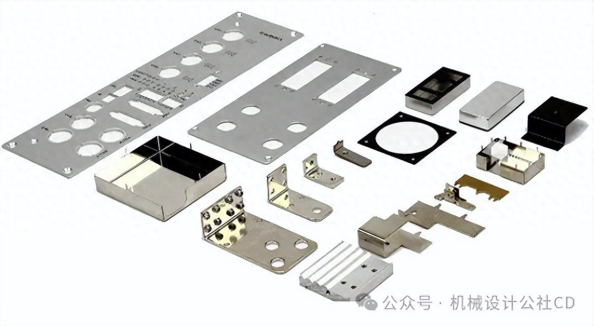

When it comes to actual processing, sheet metal manufacturing is optimised and upgraded with the help of modern processing equipment, which improves the accuracy of the parts to a greater extent and also enables the processing of more complex shapes of parts.
![图片[1]-钣金件的基础加工工艺及注意事项|钣金折弯详解-大连富泓机械有限公司](/wp-content/uploads/2026/02/1771590461908_0.jpg)
When unloading, the main unloading equipment available for sheet metal includes CNC equipment, punching equipment, shearing equipment and sawing equipment, etc. The appropriate equipment should be selected according to the requirements to enhance efficiency.
(1) Shearing machine equipment is used to shear sheet metal parts, and this shearing work needs to be completed by the shearing machine equipment, which is generally achieved with the help of the mould drop-forming technology, and is specifically applied to sheet metal parts processing, and the processing requires less precision, and at the same time, it also needs to meet the requirements of no cut-off corners of the blocks, no holes, and strips of materials.
(2) Punching equipment: To carry out multi-step processing of sheet metal parts, it is necessary to use punching equipment, with the help of punching equipment to parts to be processed, so as to improve efficiency and lower costs.
The CNC machine has to write a programme based on the graphics of the part spreading plane, and the CNC machine has to be able to recognise the programme effectively.
When flanging, the smaller base holes are processed with the aid of extractor holes during the flanging period, and the larger base holes are tapped. In the case of thin sheet metal parts, flanging enables the thickness of the sheet metal part to be expanded.
(2) Punching machines are used to process sheet metal parts with the help of moulds for shaping, so that the sheet metal parts can be processed into the corresponding shapes, and such a processing method has high precision requirements, and is mainly divided into punching, tearing, and shaping throughout the entire processing steps.
(3) Bending: To bend a sheet metal part into a 3D part, this process is called bending treatment, and this operation has to be carried out with the help of special bending moulds, or bending machines. Common bending machine moulds are mainly curved knives and straight knives. When bending aluminium sheet metal, the radius of the inner corner of the upper die bending place and the slot width of the lower die need to be upgraded.
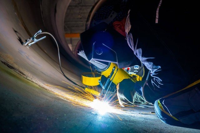
(4) Welding, sheet metal parts welding method is mainly divided into brazing, pressure welding and fusion welding so several kinds. Melt welding mainly includes manual welding, gas welding and argon arc welding. Pressure welding mainly covers the impact of welding, spot welding and butt welding; brazing is mainly a kind of electro-chrome welding. In the selection of welding methods need to process the material of the material for comprehensive consideration.
Sheet metal processing whenPoints to Note
Processing of bending, before removing the parts from the die, not to put the second piece, in the drop and punching time, to drop in time to clean up the parts on the edge of the mould. In the operation process, strictly prohibit the hand into the upper and lower die between, before taking protective measures, try to avoid the occurrence of a series of cases, the processing of small parts must be used tweezers or special tools to operate. After power failure, it is strictly prohibited to use the press that the slider will fall freely or that the operation will be continuous. Do not start the machine until the mould is tightened and the gap is adjusted.
Introduction to Sheet Metal Bending Process
![图片[2]-钣金件的基础加工工艺及注意事项|钣金折弯详解-大连富泓机械有限公司](/wp-content/uploads/2026/02/1771590461908_1.jpg)
![图片[3]-钣金件的基础加工工艺及注意事项|钣金折弯详解-大连富泓机械有限公司](/wp-content/uploads/2026/02/1771590461908_2.jpg)
Segmental bending effect
![图片[4]-钣金件的基础加工工艺及注意事项|钣金折弯详解-大连富泓机械有限公司](/wp-content/uploads/2026/02/1771590461908_3.jpg)
Bending effect
Sheet metal working principle
![图片[5]-钣金件的基础加工工艺及注意事项|钣金折弯详解-大连富泓机械有限公司](/wp-content/uploads/2026/02/1771590461908_4.png)
To know, like the following presented this kind of mould items, it belongs to the one we have the through fast 1150 CNC bending machine, this bending machine it, its pressure is 150 tonnes, it can be processed length of 3.2 m, and it has a back stop refers to the configuration of the 6 + 1 axis, in the folding of the maximum thickness of the process, for stainless steel is 4MM.
![图片[6]-钣金件的基础加工工艺及注意事项|钣金折弯详解-大连富泓机械有限公司](/wp-content/uploads/2026/02/1771590461908_5.jpg)
Can be folded into different angles of the size of the bending workpiece bending principle, is reached with the upper and lower die of the extrusion of the mould, the mould is mainly composed of the lower die and the upper die, in addition to the one-off mould, the lower die is usually with a V groove of the lower die, according to the thickness of the bending material to select a different bending lower die.
![图片[7]-钣金件的基础加工工艺及注意事项|钣金折弯详解-大连富泓机械有限公司](/wp-content/uploads/2026/02/1771590461908_6.jpg)
![图片[8]-钣金件的基础加工工艺及注意事项|钣金折弯详解-大连富泓机械有限公司](/wp-content/uploads/2026/02/1771590461908_7.jpg)
![图片[9]-钣金件的基础加工工艺及注意事项|钣金折弯详解-大连富泓机械有限公司](/wp-content/uploads/2026/02/1771590461908_8.jpg)
![图片[10]-钣金件的基础加工工艺及注意事项|钣金折弯详解-大连富泓机械有限公司](/wp-content/uploads/2026/02/1771590461908_9.jpg)
![图片[11]-钣金件的基础加工工艺及注意事项|钣金折弯详解-大连富泓机械有限公司](/wp-content/uploads/2026/02/1771590461908_10.jpg)
![图片[12]-钣金件的基础加工工艺及注意事项|钣金折弯详解-大连富泓机械有限公司](/wp-content/uploads/2026/02/1771590461908_11.jpg)
All of the above are the most commonly used bending tools in sheet metal working.
In addition, there are some special shapes, in order to ensure accuracy and improve the efficiency of processing, will also be pre-prepared for some forming moulds, such as shutters (here is just an example of it can be processed by bending machine can also be processed by punching machine). There are also commonly used arc moulds. The picture below shows the different sizes of arc moulds from R5 to R40 that we have prepared in advance (only part of the picture is taken):
![图片[13]-钣金件的基础加工工艺及注意事项|钣金折弯详解-大连富泓机械有限公司](/wp-content/uploads/2026/02/1771590461908_12.jpg)
Relying on these dies, that's mainly what happens when it comes to sheet metal bending workpiece processing. As far as these dies are concerned, they are capable of bending most of the workpieces that we commonly see.
1. Whether the bending size is sufficient
![图片[14]-钣金件的基础加工工艺及注意事项|钣金折弯详解-大连富泓机械有限公司](/wp-content/uploads/2026/02/1771590461908_13.jpg)
* Minimum bending edge corresponding to plate thickness:
As shown above, sheet metal bending consists of four parts, one is the upper die, the second is the lower die, the third is the rear positioning and the fourth is the workpiece. The upper die extrudes the workpiece towards the bottom, so that it reaches the inside of the lower V-groove, and the depth of extrusion plays a decisive role in determining the bending angle; the position of the rear locator determines the bending position and dimensions; the width of the lower V-groove of the lower die is usually 6 times the thickness of the plate, i.e. a plate of 1MM has to be made with a lower V-groove of 6MM. With this limitation, there is a minimum bending edge limit, that is, the workpiece should at least ride on both sides of the V groove, and extend the 2MM. 6mm V groove, one half of the 6MM is 3, plus the extension out of the 2mm, the result is 5mm, and this 5MM is the minimum bending edge of the 1MM plate.
Below is a table of recommended minimum bending edge sizes:
Recommended Minimum Bending Side Dimensions
Minimum bending edge means that for different plate thicknesses, the width of the V groove in the bottom die is different, usually determined in accordance with the thickness of the plate 1 to 6, the bending operation needs to be lapped on both sides, the greater the thickness of the plate, the larger the width of the groove, if the bending dimensions are too small so that the lap can not be completed, then it will not be able to complete the bending operation.
![图片[15]-钣金件的基础加工工艺及注意事项|钣金折弯详解-大连富泓机械有限公司](/wp-content/uploads/2026/02/1771590461908_15.jpg)
2、Whether bending will produce interference
When bending operations are carried out, a problem is detected that the part cannot be bent. Under what conditions can the part be bent and under what conditions can it not be bent?
Regardless of the complexity of the workpieces we process, the question of whether or not it is possible to bend them is a question of interference, in addition to the minimum bending dimensions.
Tell the crowd a tip to determine whether the interference, that is, all of our workpiece structure is envisaged as a U-shaped, in the bending of the last cut, the U-shaped back of the molding dimensions will not exceed the bending centre line?
As in the first picture, if you go out of range, you will have to use the machete in the second picture. Here we have a customised U-shape structure, which can be shaped to a maximum size of 120mm.
One small piece of advice here, design to minimise pushing the limits of factory machining, benders like these are not necessarily available in every factory, you have fewer choices of factories to choose from, dependence increases and costs go up, especially for samples.
3、Bending deformation problem
Holes and other features near bending lines
The principle of bending is actually the kind of squeezing and stretching action, and the structure near the bending line is too close to each other, so it is very easy to cause the deformation of the structure, and the edges can not be driven up. This is a problem in the hole area, but the core problem is that the edges that can't be driven can easily bulge upwards, resulting in a surface that is not flat. This is likely to have an impact on the actual presentation, as well as on possible assembly problems.


No comments