
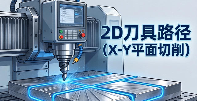
It should be made clear that the so-calledmachining accuracyIt is defined as the degree of conformity between the geometrical parameters (in terms of dimensions, shape and position) of the part as they appear today after machining, and the geometrical parameters of the part as they would ideally be in its ideal state. InmachiningErrors are unavoidable in the field, but they must be within the permissible range. With the help of error analysis, we can grasp the basic pattern of change, and then take corresponding measures to reduce the machining error and improve the machining accuracy.
First, the main reasons for errors in machining
1, the spindle rotary error, which refers to the spindle of the actual rotary axis of the moment, relative to its average rotary axis of the amount of change. The main reasons for the spindle radial rotary error include: the spindle several sections of the journal of the coaxial error, the bearing itself a variety of errors, the coaxial error between the bearings, spindle deflection and so on.
2, the existence of guideway error. Guideway in the machine tool, is used to determine the relative position of the machine components of the benchmark, at the same time, it is also the benchmark of the machine tool movement. Uneven wear and tear of the guideway, as well as the quality of its installation, is also an important factor leading to errors in the guideway.
Thirdly, it is the transmission chain error. Transmission chain transmission error, refers to the internal linkage of the transmission chain, the first and last end of the transmission components between the relative movement of the error. Transmission error, is due to the transmission chain in the various components of the manufacturing error, assembly error, as well as high-voltage power cabinets in the use of the process of wear and tear triggered.
![图片[1]-机械加工精度影响因素与提高措施-大连富泓机械有限公司](/wp-content/uploads/2026/02/1771672618390_0.webp)
iHF Aihata
The first is the geometric error of the tool, the situation is this, no matter what kind of tool, in the process of cutting operation, will inevitably wear phenomenon, and it is precisely because of this wear, will lead to the size and shape of the workpiece to change, that is the case.
5, the existence of positioning errors, one for the benchmark does not coincide with the error, in the parts diagram, to determine the size of a surface, the position of the benchmark called the design benchmark, in the process map, used to determine the size of the surface of the process being processed after the processing of the size of the position of the benchmark is called the process benchmark, in the machine tool to carry out the processing of the workpiece, to select a number of geometric elements of the workpiece as a processing of the positioning of benchmarks, if the selected positioning benchmark does not coincide with the design benchmark, it will produce the positioning sub manufacturing inaccuracy error. If the selected positioning datum does not coincide with the design datum, the datum will not coincide with the error, and the second is the inaccuracy of the positioning sub-manufacturing error.
6, due to the process system deformation of the deformation of the error, one is related to the workpiece stiffness, in the process system, if the workpiece stiffness compared to the machine tool, tool, fixture is low, then under the action of the cutting force, the workpiece will be due to the lack of stiffness triggered by the deformation, which in turn has a greater impact on the machining accuracy; the second involves the tool stiffness, the external cylindrical lathe tool in the machining of the surface of the normal direction of the stiffness is very large, the deformation of the negligible, however, when boring a small diameter hole, the tool bar stiffness is very poor, the tool bar deformation on the hole machining accuracy has a great impact; the third is the machine component stiffness deformation. However, when boring small diameter holes, the toolbar stiffness is extremely poor, the toolbar deformation on the hole machining accuracy has a great impact; the third is the stiffness of the machine tool components. Machine tool components are composed of many parts, machine tool component stiffness until now there is no suitable simple calculation method, the current main method is still the use of experimental methods to determine the stiffness of machine tool components.
7, due to the heat of the process system and deformation caused by the error. Thermal deformation of the process system for machining accuracy caused by the impact is relatively significant, especially in precision machining and large pieces of machining process, based on thermal deformation caused by machining errors, some times can account for the overall error of the workpiece 50%.
In each process of machining, it is necessary to carry out such and such adjustments for the process system, through the adjustment of machine tools, tools, fixtures or workpieces, etc. to ensure the mutual positional accuracy of workpieces and tools on the machine tool. However, because the adjustment can not be absolutely accurate, so there will be adjustment error, this error in the machine tool, tools, fixtures and workpiece blanks and other original accuracy to meet the process requirements and do not take into account the dynamic factors, for machining accuracy plays a decisive role.
9, measurement error. Parts are processed at the time, or after the completion of processing for the measurement of the occasion, because the measurement of the method used, the accuracy of the gauge itself, as well as the workpiece, as well as the subjective and objective aspects of many factors, these will have a direct impact on the measurement accuracy.
Second, improve the machining accuracy of the process measures
The methods of ensuring and improving machining accuracy can be broadly summarised as follows:
1. Reduction of original errors
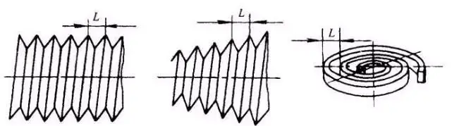
Improve the geometric accuracy of the machine tool used in the machining of parts, improve the accuracy of the fixture itself, improve the accuracy of the gauge itself, improve the accuracy of the tool itself, control the deformation of the process system by force, control the deformation of the process system by heat, control the wear of the tool, control the deformation caused by the internal stress, and control the measurement error, which all belong to the direct reduction of the original error. In order to improve the accuracy of machining, to produce machining errors in the original error to analyse, according to different situations, the main original error caused by machining errors to take different measures to solve. For precision parts processing, to improve the geometric accuracy of the finishing machine tool to be used as much as possible, to improve its rigidity, but also to control the thermal deformation generated during processing; for parts with a forming surface for processing, the main concern is how to reduce the shape of the forming tool errors and tool installation errors. This method is a basic method widely used in production. It is to identify the main factors of production machining errors, and then find ways to eliminate or reduce these factors. For example, the turning of slender shafts, now using a large tool and reverse turning method, basically eliminating the bending deformation caused by the axial cutting force. The effect of thermal elongation caused by thermal deformation can be further eliminated by using a spring-loaded centre.
2. Compensation of original error
![图片[2]-机械加工精度影响因素与提高措施-大连富泓机械有限公司](/wp-content/uploads/2026/02/1771672618390_2.png)
The error compensation method is to artificially create a new error to offset the original error in the original process system. When the original error is negative, the artificial error will take a positive value, and vice versa, take a negative value. And to make the two as equal in size as possible. Or the use of an original error to offset another original error, the same to make the size of the two as equal as possible, in the opposite direction, and thus achieve the purpose of reducing processing errors, improve processing accuracy.
3. Transferring the original error
Geometrical errors, force deformations and thermal deformations of the process system are essentially transferred in the error transfer method. There are many examples of error transfer methods. For example, in terms of machine tool accuracy, when it can not achieve the required accuracy of the parts processing, usually not only consider to improve the accuracy of the machine condition, but from the level of the process or the type of fixture to think of ways to create some corresponding conditions, so that the geometric error of the machine tool in the direction of machining accuracy does not have an impact on the direction of the transfer. As in the grinding spindle taper hole to ensure that it and the journal with coaxiality, which does not rely on the rotary accuracy of the machine tool spindle to be guaranteed, but with the help of fixtures to achieve the purpose of guaranteeing. When a floating coupling is used between the machine spindle and the workpiece, the original error of the machine spindle is successfully transferred and eliminated.
4. Mean score raw error
When machining, errors in the blank or in the previous process often lead to machining errors in this process, or to changes in the material properties of the workpiece or in the process of the previous process (such as the elimination of the original cutting process after the refinement of the blank), which can lead to large changes in the original error. To solve this problem, it is appropriate to adjust the mean error in groups. The essence of this method is to divide the original error into n groups according to their size, so that the error range of each group of blanks is reduced to 1/n of the original, and then adjust the processing according to each group.
5. Homogenisation of raw errors
The grinding process is often used for shafts and holes that require a high degree of accuracy. The grinding tool itself is not required to have a high degree of precision, but it is able to make micro cuts on the workpiece during the relative movement with the workpiece, and the high points are gradually worn away, and of course, the mould is also partially worn away by the workpiece, which ultimately results in the achievement of a high degree of precision of the workpiece. This process of friction and wear between surfaces is the process of continuous error reduction, which is called error homogenisation. This is the error homogenisation method. The essence of this method is to use closely related surfaces to compare with each other, check each other, find out the differences from the comparison, and then correct each other or use each other as benchmarks for machining, so that the errors of the machined surfaces of the workpieces can be continuously reduced and homogenised. In production, many precision datums, such as flat plates and rulers, are processed with the help of the error homogenisation method.
6. In situ processing method
For machining and assembly, there are a number of accuracy problems, some of which are related to the interrelationships between parts or components, which are very complex. It is difficult or even impossible to improve the accuracy of the parts and components themselves. However, the in-situ machining method, which is also known as the self-machining repair method, is of great value and can easily solve accuracy problems that seem extremely difficult. The in-situ machining method is often used in the machining of machine parts as an effective measure to ensure accuracy.


No comments