


The standard procedure for a CNC machining centre typically consists of seven steps, each of which must be carried out in sequence. Failure to follow the sequence of the standard procedure can easily lead to machine malfunctions or pose a risk to personal safety; staff must therefore exercise particular caution.
1. Ensure everything is ready before switching on
Whenever the power is switched on, or following an emergency stop and reset, the machine returns to its reference zero position—that is, it performs a zero-point calibration—thereby establishing a reference position for subsequent operations.
2. Workpiece clamping
Before cleaning the surface of a workpiece, it must first be thoroughly cleaned to ensure it is free from oil, iron filings and dust; any burrs on the surface must be removed using a file or an oilstone. The surface of the fixture must be ground and polished to ensure it is flat and smooth.
The clamping blocks and nuts must be secure and capable of holding the workpiece firmly in place. If you encounter small workpieces that are difficult to position, they can be clamped directly onto the vice jaws. The machine must be kept clean and free of metal shavings, dust and oil; At the four corners of the workpiece, if the central section is too large, a raised corner must be added in the middle. Check the length and width of the workpiece against the drawing dimensions using a ruler to ensure they meet the requirements.
When mounting the workpiece, follow the mounting instructions specified in the programme to prevent the fixture from coming into contact with the machining area or the cutting tool.
Once the workpiece has been placed on the tailstock, the reference surface of the workpiece must be set in accordance with the drawing specifications. For workpieces that have already been machined on both sides, the perpendicularity must be checked to ensure it meets the requirements. Once the workpiece has been clamped in place, the nuts must be tightened to prevent the clamp from becoming loose and causing the workpiece to shift during machining; then, take a measurement to check for any errors. If an error is found, it must be corrected. The perpendicularity must be checked to ensure it meets the requirements.
Once the workpiece has been drawn, it is essential to tighten the nut to prevent the clamp from becoming loose, thereby avoiding any displacement of the workpiece during the machining process; the drawing operation should then be carried out once more. If an error is subsequently identified, the situation is rather problematic.
To check whether the verticality meets the standard, it is essential to tighten the nut after drawing the workpiece. This prevents the clamp from becoming loose, which could cause the workpiece to shift during machining. A dial gauge check should then be carried out; if an error is detected, it is difficult to rectify.
3. Number of workpiece contacts
The workpiece can be clamped using a reference zero determined by the number of contact points. The contact points may be either photoelectric or mechanical, and there are two types of contact methods: single-sided and double-sided. The contact procedure is as follows: photoelectric and electrostatic for photoelectric contact points, and mechanical for mechanical contact points, with a rotational speed of 450 rpm.
Manually move the worktable along the X-axis during the probing process to bring the probe into contact with one side of the workpiece; when the probe makes contact with the workpiece and the red light illuminates, set the relative coordinates of that point to zero; Move the X-axis to contact the other side of the workpiece. The relative coordinates at the moment the probe touches the workpiece are then used; subtract the probe’s diameter from this value to obtain the workpiece’s length.
Divide the relative coordinate value by 2; this value becomes the midpoint of the workpiece on the X-axis. Next, move the worktable to the midpoint of the X-axis, then set the relative coordinate value of the X-axis to zero; this is known as the workpiece zero point on the X-axis. Use one of the G54–G59 commands to record the mechanical coordinates of the workpiece’s X-axis zero point, thereby allowing the machine tool to establish the workpiece’s X-axis zero point. Verify the accuracy of the data once again. The procedure for setting the workpiece’s Y-axis to zero is the same as for the X-axis.
4. Prepare the tools
Using the tool data provided in the programming instructions, change to the tool to be used for machining so that it strikes the height gauge positioned on the reference plane; when the indicator light comes on, set the relative coordinate value to zero. Then move the tool to the safety position, manually lower it by 50 mm, and set the relative coordinate value to zero again. This is the zero point on the Z-axis.
The Z-coordinate of the point in question is recorded in one of the G54 to G59 commands. In this way, the workpiece is zeroed on the X-axis, the Y-axis and the Z-axis.
Check the accuracy of the data once again; the probing method used on the other side also involves probing one side of the workpiece along the X or Y axis. The point corresponding to the coordinate values of the X and Y axes and the probe tip radius is the origin of the X and Y axes. The mechanical coordinates of the X and Y axes are recorded in one of the parameters G54 to G59. Check the accuracy of the data once more, verify the accuracy of the origin, and move the X and Y axes towards the workpiece.
Check the accuracy of the zero point based on the dimensions of the workpiece. Copy the programme file to your computer using the file path specified in the programming guide.
5. Parameter settings
Setting the spindle speed during machining: N = 1000 × V / (3.14 × D)
N: Spindle speed (rpm/min)
V: Cutting speed (m/min)
D: Tool diameter (mm)
Machining feed rate setting: F = N × M × Fn
F: Feed rate (mm/min)
M: Number of blades
Fn: Tool feed rate (mm/rev)
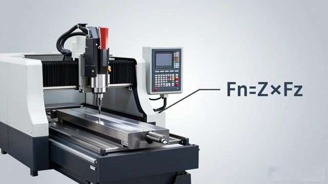
Setting the feed per tooth: Fn = Z × Fz
Z: Number of cutting edges
Fz: Feed rate per cutting edge (mm/rev)
6. Preparing for processing
At the start of each programme, you must carefully check that the tool you are using is the one specified in the instruction manual. Activate the CNC machining feed, reduce the feed rate to the minimum, use single-block execution, perform rapid positioning, and commence the cutting operation. Feed movements must be concentrated; keep your hand on the stop button and halt immediately should any issues arise. Pay close attention to the direction of the tool’s movement to ensure safety, then gradually increase the feed rate to an appropriate level. Coolant or cool air must be applied to both the tool and the workpiece. During CNC roughing operations, do not stray too far from the control panel; should any abnormalities occur, stop the machine immediately for inspection.
Pull the workbench forward and check again and again to ensure the workpiece is not loose. If it is, you will need to recalibrate and adjust the reading.
We are in the process of continuously optimising CNC machining parameters to achieve the best possible results. As this is a critical stage in the process, once the CNC machining of the workpiece is complete, the key dimensions must be measured to verify that they conform to the drawing. Should any issues arise, the team leader or programmer must be notified immediately for inspection. Once resolved, the workpiece must be tested independently and submitted to the inspector for a specific inspection.
When machining holes on a CNC machining centre, the drilling process must begin with positioning using a centre drill. This is followed by drilling with a drill bit that is 0.5 to 2 mm smaller than the dimension specified on the drawing, and finally, a suitable drill bit is used to carry out the CNC finishing operation.
When reaming a workpiece, the first step is to centre it using a centre drill, followed by drilling a hole with a drill bit that is 0.5 to 0.3 millimetres smaller than the dimension specified in the drawing, and finally, a reamer is used to ream the hole. During the reaming process, the spindle speed must be maintained at between 70 and 180 revolutions per minute.
The boring process is as follows: first, the workpiece is centred using a centre drill; next, a drill bit 1 to 2 millimetres smaller than the dimension specified on the drawing is used to bore the hole; then, machining is carried out using a rough boring bar or milling cutter until approximately 0.3 mm remains on one side, along with a suitable machining allowance. Finally, finish boring is performed using a pre-set finish boring bar, with the final finish boring allowance not to be less than 0.1 mm. Direct CNC refers to DNC operation. The procedure is as follows: before commencing DNC machining, the workpiece must be securely clamped, zeroed, and the parameters set. thereafter, check the number of open machining programmes on the computer, then switch the computer to DNC mode, and enter the correct filename of the machining programme, including punctuation. Press the TAPE key on the machine, then press the program start key; at this point, the machine controller will display the word ‘LSK’ in a flashing state.
7. Worker self-inspection
Before commencing CNC machining, the operator must review the contents of the process card, familiarise themselves with the workpiece’s specifications, understand its shape and examine the drawings carefully; only then can they determine the scope of the machining process. Before clamping the workpiece, the dimensions of the blank should be measured to ensure they comply with the drawing specifications. When the installation and programming instructions align with the manual, the workpiece must be examined carefully and thoroughly. Following rough machining, a self-inspection should be carried out promptly to enable timely adjustments to any dimensional deviations. The scope of the self-inspection largely depends on the size of the machining area. For example, one should check whether the workpiece is loose; verify that the workpiece has been correctly positioned; confirm that the dimensions of the CNC-machined parts relative to the reference edge (reference point) match the drawing requirements; and check the positional dimensions between machined parts.
Once the self-check has been completed. Once CNC machining has been completed, the operator should process the workpiece.
The shape and dimensions of the workpiece are subject to self-inspection. First, the vertical surfaces at the CNC machining site are checked, followed by verification of the basic length and width dimensions. The gradients and basic dimensions specified on the drawings are then measured at the machining site. Once the workers have completed the self-inspection of the workpieces and confirmed which ones comply with the drawings and process requirements, the inspection staff will then carry out a specialised inspection.
 Chinese
  Japanese
  English
  German
  Finnish
Leave a Reply
You must be logged in to post a comment.