
1. Subject matter and scope of application
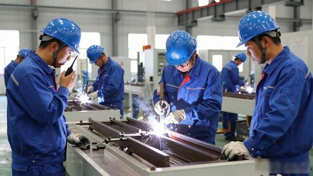
This standard specifies the operating procedures for the machining of riveted and welded components.
This standard applies to the machining of riveted and welded components at this factory.
2. Referenced standards
YB/JQ101.10 sets out the general technical specifications for mechanical repair and manufacturing in the steel industry, covering, amongst other things,Welded structural parts.
GB152 nail hole diameter
3. Preparation before processing
Before commencing machining, one should familiarise oneself with the drawings and the process requirements, and ensure that all relevant equipment is ready for use, along with the necessary tools, templates and measuring instruments.
4. Machining of workpieces
4.1 Shearing
4. Before carrying out the shearing operation described in 1.1, the material of the workpiece must be verified, and it must be checked to ensure that it meets the requirements set by the shearing machine regarding the initial cut.
4. Clear the site, check the operational status of the equipment, carry out a test run, and only commence work once everything has been confirmed to be in good working order. This should be carried out in accordance with section 1.2.
4.1.3 Select the cutting sequence according to the incoming material and adjust the cutting gap to the appropriate setting.
4. When carrying out the shearing operation described in section 1.4, it is essential to clearly distinguish between each type of marking line and to perform the shearing in accordance with the stamped shearing lines, ensuring that the upper cutting edge is precisely aligned with the shearing line. For the permissible shearing deviation relative to the shearing line, please refer to Table 1 for specific details.
Table 1: Permissible deviations for shearing (mm)
Length of shear line Plate thickness
≤2 3–5 1–16
Permissible tolerance ±
>100 0.5 1.0 1.0
100–250 0.5 1.0 1.0
250–1000 1.0 1.0 1.5
1000–1500 1.0 1.0 2.0
1500–2000 1.5 2.0 2.0

4.1.5 When working in a group, members must co-operate closely and follow the instructions of a single person in charge.
4.2 Machining of Holes
4. With regard to the hole referred to in section 2.1, the machining method should be selected in accordance with the process requirements or machining conditions, and it is essential to clearly identify the purpose of this hole in the subsequent process.
4. When carrying out the drilling operation described in Section 2.2, the operating procedures for drilling must be followed. When drilling with an electric drill, operators must coordinate with one another, hold the drill steady, ensure the workpiece is securely clamped, and keep the drill bit perpendicular to the work surface!
4.2.3 Cylindrical parts should be drilled prior to bending; the diameter of the holes drilled should be 1 to 2 millimetres smaller than the standard hole diameter, in order to allow for reaming to correct the dimensions after bending.
4. When drilling, ensure the dimensions are correct, select the appropriate cutting parameters, and prepare the coolant. The method of clamping the workpiece is crucial; it must be clamped straight. The clamping force must be appropriate, and when turning by hand, apply force evenly with both hands to prevent defects.
4.2.5 The workpiece must be correctly clamped during tapping; lubricant should be applied frequently to improve accuracy.
4.2.6 Machining of assembly holes shall be carried out in accordance with the process requirements.
4.2.7 Machining of assembly holes shall be carried out in accordance with the process requirements.
4.3 Machining of Weld Grooves
4.3.1 Gain a detailed understanding of the groove types and machining requirements in accordance with the process documentation.
4. In accordance with the process requirements, the machining method for the 3.2 groove is selected; alternatively, the machining conditions are defined based on the required groove accuracy, and the machining method for the 3.2 groove is then selected.
4. For the air chisel machining described in 3.2.1, the cutting angle of the air chisel head should be set at around 50°, and the chisel head must be adequately lubricated.
When machining using the edge-planing machine described in 4.3.2.2, the machine’s operating condition must first be checked, and lubricant must be applied to the specified areas. All edge-planing operations require a 2 to 4 millimetre allowance to be left.
4.3.2.3 For oxy-fuel cutting of grooves, follow the relevant operating procedures for oxy-fuel cutting.
4. At 3.24, when machining the groove using a carbon arc air gouging process, one should work as far as possible in the direction of the wind. Once gouging is complete, the arc should be broken first; after a few seconds, the gas valve should then be shut off.
4.4 Correction
4.4.1 Preparations prior to correction
4. Inspect the workpiece requiring straightening; based on the drawings, gain a thorough understanding of the extent of the deformation, identify the type of deformation, analyse the causes of the deformation, and, at the same time, devise a method for straightening it.
4. First, remove any burrs from the workpiece, then remove the scale, followed by any spatter, and finally check for cracks.
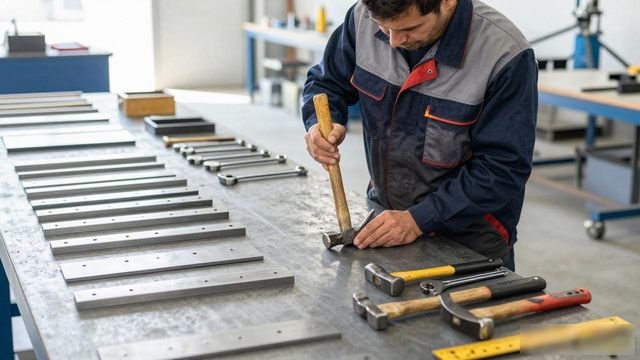
4.4.1.3 When carrying out manual straightening, ensure that the workbench, the necessary tools, measuring instruments and simple machinery are all ready. When using a hammer, check that the handle and head are securely fastened.
4.4.1.4 When using the machine for correction, it should first be calibrated to ensure it is operating correctly.
4.4.1.5 Where flame straightening is used, a heat source must be provided.
4.4.2 Correction procedures
4. For thin plates and small-section structural steel, manual straightening methods may be used; however, for thick plates and large-section structural steel, a combination of mechanical straightening and flame straightening is required.
4.4.2.2 The correction process must be determined on the basis of the material specifications, and must also take into account the type and extent of deformation. For workpieces with complex deformations, care must be taken regarding the sequence of correction. Generally, complex deformations are corrected first, followed by simpler ones.
4.4.2.3 When straightening workpieces by hand, the depth of the hammer marks must not exceed 0.5 mm. For critical workpieces, the sledgehammer must under no circumstances be struck directly against the steel plate; instead, a flat surface must first be placed beneath the workpiece before striking it with the hammer.
4. When four people are using sledgehammers to straighten a sheet of metal at the same time, they must follow the instructions of the person holding the lead hammer; they must not swing their hammers before being told to do so, nor must they drop their hammers.
4. With regard to the use of a rolling straightening machine such as that described in 4.2.5 to correct distorted materials, firstly, the gap between the rollers must be adjusted according to the degree of deformation; furthermore, the sheet must move in synchronisation with the rollers, and slippage must not be permitted.
4.4.2.6 When straightening workpieces using a press, springback must be taken into account. During the straightening process, repeated trials should be carried out, and the amount of pressure applied should be adjusted according to the results.
4.4.2.7 Structural steel should, where possible, be straightened using the threaded rod pressing method.
4.4.2.8 When performing flame straightening, care must be taken to consider the material to avoid quenching cracks. The heating temperature is typically between 700 and 800 °C; striking must not be carried out within the blue-brittle zone (200–500 °C).
4.4.2.9 When performing flame straightening, the correct heating position and heating method must be selected.
a. If the first heating correction is unsuccessful, a second heating cycle may be carried out; the heating location must be offset from the previous one, and the heating points must not be repeated.
b) When carrying out spot heating, the size of the heated spot is determined by the thickness of the plate; the distance between spots is generally within the range of 50 to 100 mm.
c) The width of the line-heating zone is typically between approximately 0.5 and 2 times the thickness of the steel plate; this method is frequently used in structures with large deformation zones.
d) Triangular heating is used to correct bending deformation in components with high rigidity.
4.4.2.10 Water-and-flame straightening is used for steel plates up to 8 mm thick; the distance between the water and the flame increases as the thickness of the steel increases, and this distance generally does not exceed 30 mm. For workpieces thicker than 40 mm, water cooling must not be used during flame straightening.
4.4.2.11 The effectiveness of the correction must be checked at all times during the correction process.
4. Upon inspection, workpieces that meet the requirements are those produced following the process described in 4.3 ‘Workpiece Rectification’. Such workpieces must be stored carefully and must not be thrown about.
 Chinese
  Japanese
  English
  German
  Finnish
Leave a Reply
You must be logged in to post a comment.