
An Automatic Wire-Threading Device and Method for an Electric Discharge Wire-Cut Machining Centre
technical field
The present invention relates to a device, namely an automatic wire-threading device for an electric discharge wire-cutting machine. More specifically, this automatic wire-threading device for an electric discharge wire-cutting machine also relates to a wire-threading method. In particular, this device and wire-threading method are suitable for high-speed wire-fed electric discharge wire-cutting machines.
Background Technology
China’s independently developed high-speed wire-cut EDM machine is capable of machining workpieces with significant thickness and taper. With a low purchase price (40,000–50,000 yuan), it is currently one of the most widely used machine tools in the country, offering unique advantages and broad market prospects in fields such as mould manufacturing. However, the economic benefits offered by high-speed wire-cut EDM machines fall far short of those provided by low-speed unidirectional wire-cut EDM machines. Even with the current adoption of multi-pass cutting technology, intelligent wire magazine control systems and intelligent tension control systems—which can significantly improve the machining accuracy of wire-cut EDM— Nevertheless, a common and significant defect persists in actual production: wire breakage.
At present, threading on existing high-speed wire-cut EDM machines is carried out manually, Thread threading is a time-consuming, labour-intensive and technically demanding task; achieving proficiency and speed requires extensive training. In an era where efficiency and automation are prioritised whilst maintaining quality, the installation of an automatic threading device on the machine tool it would improve the wire-threading environment, reduce the difficulty of the task, and significantly shorten the time required for threading. This would enhance the machine’s level of automation and boost production efficiency.
Summary of the Invention
The technical problem addressed by the present invention is to provide an automatic wire-threading device for an electric discharge wire-cutting machine tool, which is capable of automatically performing the wire feeding and threading operations throughout the entire threading process, together with a corresponding wire-threading method.
An automatic wire-threading device for an electric discharge wire-cutting machine employs the following technical solution: the device comprises a wire-clamping mechanism, a wire-feeding mechanism and a wire-pulling mechanism. The wire-clamping mechanism is further divided into a wire-clamping mechanism for the upper wire arm and a wire-clamping mechanism for the lower wire arm. The wire-feeding mechanism is positioned below and to the outside of the guide roller on the right-hand side of the upper wire arm, The wire clamping mechanism of the upper wire arm is mounted on the lead screw of the upper wire arm; it is used to clamp the electrode wire and guide it to move towards the right-hand side of the upper wire arm, passing through the guide pulley on the right-hand side of the upper wire arm, before being fed into the wire feeding unit of the wire feeding mechanism. The wire feeding mechanism is used to grip the electrode wire and feed it downwards; The wire clamping mechanism on the lower wire arm clamps the electrode wire fed by the wire feeding mechanism and pulls it towards the left side of the lower wire arm, thereby completing the automatic threading process; The wire-guiding mechanism comprises the upper wire arm’s wire-guiding mechanism and the lower wire arm’s wire-guiding mechanism; these are respectively secured to the wire arms via fixed brackets. The fixed brackets comprise a first fixed bracket and a second fixed bracket, with a guide rod positioned between the first and second fixed brackets, A fixed support plate is mounted on the guide rod, and a lead screw is positioned between the fixed support plate and the second fixed bracket. The assembly also comprises a sliding base, which is mounted on the lead screw and guide rod and is capable of moving along the axis of the lead screw. Furthermore, it comprises a first stepper motor, mounted on the fixed support plate, with its output shaft connected to the lead screw and maintained in coaxial alignment, providing power for the rotation of the lead screw; the lead screw guides the sliding base, ensuring that the sliding base cannot rotate but can only move along the axis of the lead screw; The forward and reverse rotation of the first stepper motor drives the forward and reverse rotation of the lead screw, thereby causing the sliding base to move back and forth along the axis of the lead screw; The wire-clamping mechanism is secured to the sliding base via the wire-clamping base; it comprises a first wire-clamping body and a second wire-clamping body. The first and second wire-clamping bodies act in concert to clamp or release the electrode wire situated between them, and their direction of movement is perpendicular to that of the sliding base; The second wire-clamping body is mounted via a rotary shaft in conjunction with a rotary shaft housing, enabling the first and second wire-clamping bodies to rotate about the rotary shaft housing; the rotary shaft housing is fixedly mounted on the wire-clamping base. The assembly also comprises a first push-pull solenoid mounted on the second wire-clamping body, which provides the driving force for the movement of the first wire-clamping body, thereby causing the first and second wire-clamping bodies to clamp or release the electrode wire; it also comprises a second stepper motor fixedly connected to the rotary shaft, which provides the driving force for the rotation of the rotary shaft about the rotary shaft housing; The wire-feeding mechanism comprises a mechanism housing, a wire-feeding housing, a second push-pull solenoid, a lever, a lever restraint, and a wire-feeding body. The lever restraint secures the mid-point of the lever to the mechanism housing or the upper wire arm, allowing the lever to rotate only about the lever restraint, The mechanism housing is fixedly connected to the upper wire arm, and the wire-feeding housing is fixed to the mechanism housing; the second push-pull solenoid is fixed to the mechanism housing to provide the driving force for the lever’s oscillation, whereby the lever’s oscillation drives the wire-feeding body to move up and down through the wire-feeding housing; The wire-feeding body is perforated with a hole through which the electrode wire can pass; the upper section of the wire-feeding body is wider than the section immediately below it. When the wire-feeding body moves downwards, the wire-feeding housing clamps the upper end of the wire-feeding body, thereby clamping the electrode wire, When the wire-feeding body moves upwards, its upper end disengages from the wire-feeding housing, thereby releasing the electrode wire.
When the first push-pull electromagnet is energised, the electromagnet spring contracts, thereby driving the first clamping body to move towards the second clamping body, ultimately achieving the clamping of the electrode wire; When the first push-pull solenoid is de-energised, the solenoid spring extends, causing the first wire-clamping body to spring back automatically, thereby causing the first wire-clamping body to separate from the second wire-clamping body, thus releasing the electrode wire. When the electrode wire is transported to the right-hand side of the upper wire-feeding arm, the wire-clamping body, driven by the second stepper motor, rotates 90 degrees clockwise.
If the second push-pull solenoid is de-energised, the solenoid spring will extend, thereby pushing the lever to rotate anti-clockwise, causing the wire-feeding unit to move upwards. The upper end of the wire-feeding unit opens, releasing the electrode wire, which remains at rest as it is no longer under tension; If the second push-pull solenoid is energised, the solenoid spring contracts, pulling the lever to rotate clockwise, driving the wire-feeding unit downwards; the upper end of the wire-feeding unit is compressed and closes, clamping the electrode wire and moving it downwards together. Throughout this process, the continuous repetition of de-energising and energising the second push-pull solenoid enables the electrode wire to be fed downwards.
It also comprises a ball-joint housing, which is securely connected to the second push-pull magnetic stabiliser; both ends of the lever are ball-shaped, with the ball at one end housed within the ball-joint housing and the ball at the other end seated in a groove in the wire-feeding body.
This also includes the stop ring, which is fixed in place in front of the wire feeder; its function is to limit the distance the wire feeder can move upwards.
The wire-feeding assembly referred to above comprises the upper wire-feeding unit and the lower wire-feeding unit; the oscillation of the lever causes the lower wire-feeding unit to move up and down, and this vertical movement of the lower wire-feeding unit in turn drives the upper wire-feeding unit to move up and down.
The other end of the lever is positioned within a groove in the lower section of the wire feeder.
The stop ring described is fixedly mounted on the lower section of the wire-feeding unit.
Furthermore, there is a wire-feeding mechanism, which is fixedly mounted beneath the wire-feeding assembly; this mechanism comprises a wire-feeding housing, a wire-feeding nozzle and a spray nozzle; the wire-feeding nozzle is positioned inside the spray nozzle, and its function is to guide the electrode wire through its interior; The wire-guiding housing is fixedly connected to the nozzle, and the assembled unit forms a hollow chamber; this chamber is designed to contain high-pressure water; High-pressure water enters the cavity through an orifice on the side of the wire-guiding housing, after which the nozzle ejects the high-pressure water, thereby driving the movement of the electrode wire within the wire-guiding nozzle. Guided by the water-guided wire mechanism, the electrode wire can more easily enter the space between the first and second wire clamps on the lower wire arm.
The wire-reinforced base is secured to the sliding base using bolts inserted into the bolt slots.

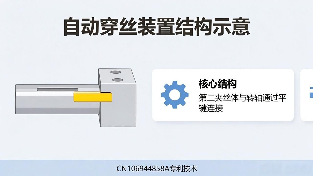
The second clamping member and the rotary shaft are connected by a flat key in the keyway.
The aforementioned spindle housing is secured to the wire-clamping base via bolt slots.
The first push-pull electromagnet is secured to the second wire-clamping body by bolts.
With regard to the automatic wire-threading method corresponding to the automatic wire-threading device described above, the specific procedure is as follows: Firstly, the operator manually pulls the electrode wire towards the wire-clamping mechanism on the upper threading arm; Second, current is applied to the first push-pull type electromagnet within the wire-clamping mechanism of the upper wire arm, causing the clamping mechanism to grip the electrode wire firmly; Thirdly, the first stepper motor of the upper threading arm drives the lead screw to rotate, thereby causing the mechanism comprising the upper threading arm’s wire-clamping mechanism and the sliding base to move to the right; when it reaches a preset position, the first stepper motor of the upper threading arm ceases operation; Step 4: The second stepper motor in the upper wire arm’s clamping mechanism drives the first and second clamping bodies to rotate 90 degrees clockwise, guiding the electrode wire through the guide roller on the right-hand side of the upper wire arm and feeding it into the upper section of the middle part of the wire feeder body within the wire feeding mechanism, which is currently de-energised; Step 5: The second push-pull solenoid in the wire feeding mechanism repeatedly switches the current on and off, driving the electrode wire within the wire feeder downwards until it reaches the wire clamping mechanism on the lower wire arm; Step 6: The current to the second push-pull solenoid is cut off, and the wire clamping mechanism on the lower wire arm securely locks the electrode wire whilst the first push-pull solenoid carried by the mechanism is active; Step 7: The first stepper motor on the lower wire arm drives the lead screw, causing the wire clamping mechanism to move to the left until it reaches the preset position, at which point it stops; Step 8: The operator winds the electrode wire onto the spool, thereby completing the threading process.
Step 1: An operator manually guides the electrode wire to the wire-clamping mechanism on the upper wire-feeding arm. Step 2: The first push-pull solenoid in the wire-clamping mechanism of the upper wire-feeding arm is energised, causing the mechanism to clamp the electrode wire. Step 3: The first stepper motor on the upper wire arm rotates the lead screw, causing the mechanism comprising the upper wire arm clamping mechanism and the sliding base to move to the right; once it reaches the set position, the first stepper motor on the upper wire arm stops operating. Step 4: the second stepper motor of the upper wire arm’s wire clamping mechanism rotates the first and second clamping bodies 90 degrees clockwise, guiding the electrode wire through the guide pulley on the right-hand side of the upper wire arm and into the upper end of the wire feeding body of the wire feeding mechanism (which is de-energised at this stage); Step 5, The second push-pull solenoid of the wire-feeding mechanism is repeatedly energised and de-energised, driving the electrode wire within the feed body to move downwards until it is fed into the water-guided wire mechanism. Step 6, The second push-pull solenoid is de-energised, and the high-pressure pump delivers high-pressure water into the water-guided wire mechanism, transporting the electrode wire downwards until it reaches the wire-clamping mechanism on the lower wire arm. Step 7, The wire clamping mechanism on the lower wire arm clamps the electrode wire under the action of its first push-pull solenoid. Step 8: The first stepper motor on the lower wire arm drives the lead screw, moving the wire clamping mechanism to the left until it reaches the preset position, at which point it stops. Step 9: The operator winds the electrode wire onto the spool, thereby completing the threading process.
The beneficial effect of the present invention is that, compared with the prior art, it comprises a complete set of wire clamping mechanisms, as well as a wire-feeding mechanism and a wire-advancing mechanism. It overcomes the previous limitation whereby only a small portion of the threading process could be automated; it effectively resolves the issue of automatic wire feeding in automatic threading devices, whilst also addressing the problem of automatic threading. It can completely replace manual threading and wire feeding operations on the machine tool and is a key technology for enabling automatic threading in high-speed reciprocating wire-cut EDM machines.
illustrate
It is equipped with a wire clamping mechanism, a wire feeding mechanism and a wire pulling mechanism; Figure 1 is an assembly diagram illustrating an embodiment of the present invention comprising these three mechanisms.
Figure 2 shows a schematic diagram of the filament-drawing mechanism in one embodiment of the present invention.
Figure 3 shows a three-dimensional view of the filament-drawing mechanism of the embodiment illustrated in Figure 2.
Figure 4 shows a schematic diagram of the wire-clamping mechanism in one embodiment of the present invention.
Figure 5 is a cross-sectional view of the wire-clamping mechanism shown in the embodiment illustrated in Figure 4; Figure 6 is a schematic diagram of the wire-feeding mechanism in one embodiment of the present invention.
Figure 7 shows a schematic diagram of the structure of the wire-feeding upper body of the wire-feeding mechanism in one embodiment of the present invention.
Figure 8 shows a schematic diagram of the structure of the wire-pulling mechanism in one embodiment of the present invention.
Figure 9 is a cross-sectional three-dimensional view of the water-guided wire mechanism shown in the embodiment of the present invention illustrated in Figure 8.
Figure 10 shows a schematic diagram of the push-pull electromagnet core structure in one embodiment of the present invention.
practical way of doing sth.
To make the objectives, technical solutions and advantages of the present invention clearer, the invention is described in further detail below with reference to the accompanying drawings and examples. It should be understood that the specific examples described herein are intended merely to illustrate the invention and are not intended to limit it.
In this specification, any feature disclosed in the abstract or the accompanying drawings may, unless specifically stated otherwise, be replaced by other alternative features that are equivalent or serve a similar purpose. In other words, unless otherwise stated, each feature is merely one example among a range of equivalent or similar features.
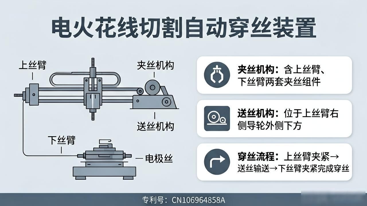
There is an automatic wire-threading device for an electric discharge wire-cutting machine; specific embodiment i is shown in Figure 1, which comprises a wire-clamping mechanism 5, a wire-feeding mechanism 7 and a wire-pulling mechanism 6. The wire clamping mechanism 5 is further divided into the wire clamping mechanism of the upper wire arm 8 and the wire clamping mechanism of the lower wire arm 9. The wire feeding mechanism 7 is situated below and to the outside of the guide wheel on the right-hand side of the upper wire arm. The wire clamping mechanism of the upper wire arm is mounted on the lead screw of the upper wire arm; its function is to clamp the electrode wire 3 and pull it towards the right-hand side of the upper wire arm, so that it passes through the guide pulley 4 on the right-hand side of the upper wire arm and is fed into the wire feeding unit of the wire feeding mechanism. The wire feeding mechanism is used to grip the electrode wire and feed it downwards. The wire clamping mechanism on the lower wire arm grips the electrode wire fed by the wire feeding mechanism and pulls it towards the left-hand side of the lower wire arm, thereby completing the automatic threading process.
In this specific embodiment, the cutting machine 1 uses the column 10 to secure the upper and lower wire arms, with the wire spools 2 positioned on the left-hand side of the upper and lower wire arms.
As shown in Figure 2, the filament feeding mechanism for the upper filament arm is secured to the filament arm via a fixed support assembly, which comprises a first fixed support 61 and a second fixed support 67. As shown in Figure 3, the wire-pulling mechanism of the lower wire arm is likewise secured to the wire arm via a fixed support bracket, which also comprises a first fixed support bracket 61 and a second fixed support bracket 67. A smooth rod 66 is provided between the first and second fixed support brackets, and a fixed support plate 63 is mounted on the smooth rod. A lead screw 64 is positioned between the fixed support plate and the second fixed bracket. There is also a sliding base 65, which is mounted on the lead screw and the guide rod and is capable of moving along the axis of the lead screw. In addition, a first stepper motor 62 is mounted on the fixed support plate; its output shaft is connected to the lead screw and maintained in coaxial alignment with it, providing the power for the lead screw to rotate. The lead screw guides the sliding base, preventing it from rotating and allowing it to move only along the axis of the lead screw.
When the first-stage stepper motor rotates forwards, it drives the lead screw to rotate forwards, allowing the sliding base to move backwards along the lead screw’s axis; when the first-stage stepper motor rotates backwards, it drives the lead screw to rotate backwards, allowing the sliding base to move forwards along the lead screw’s axis.
As shown in Figures 4 and 5, the wire-clamping mechanism is secured to the sliding base by means of the wire-clamping base 56; the wire-clamping mechanism comprises a first wire-clamping body 51 and a second wire-clamping body 52. The first wire-clamping body and the second wire-clamping body work together to clamp or release the electrode wire situated between them, and the directions of movement of both are perpendicular to the direction of movement of the sliding base 65. The second wire-clamping body is mounted on the pivot shaft 53 in conjunction with the pivot shaft housing 58, thereby allowing the first and second wire-clamping bodies to rotate about the pivot shaft housing. The pivot mount 58 is fixedly mounted on the wire-clamping base. The wire-clamping mechanism also comprises a first push-pull solenoid 54 mounted on the second wire-clamping body, which provides the driving force for the movement of the first wire-clamping body, thereby causing the first and second wire-clamping bodies to clamp or release the electrode wire. The wire clamping mechanism further comprises a second stepper motor 55, which is fixedly connected to the rotary shaft and provides the driving force for the rotary shaft to rotate around the rotary shaft housing. In this specific embodiment, the wire clamping base 56 is secured to the sliding base by bolts via bolt slots. The second wire-clamping body and the rotary shaft are connected via a flat key in keyway 59. The rotary shaft housing is mounted and secured to the wire-clamping base via bolt slots 57. The first push-pull solenoid is secured to the second wire-clamping body by bolts. In this specific embodiment, the wire-clamping mechanism is mounted on the wire arm by means of bolts.
As shown in Figure 6, there is a wire-feeding mechanism comprising a mechanism housing (71), a wire-feeding housing (78), a second push-pull solenoid (72), a lever (74), a lever restraint (75) and wire-feeding bodies (76 and 79); The lever restraint secures the centre of the lever to the mechanism housing or the upper wire arm, such that the lever can only rotate about the lever restraint; this mechanism housing is fixedly connected to the upper wire arm, and the wire-feeding housing is fixed to the mechanism housing; The second push-pull solenoid is fixed to the mechanism housing and provides the driving force for the lever’s oscillation; the oscillation of the lever causes the wire-feeding body to move up and down through the wire-feeding housing; the wire-feeding body has a wire hole (1) through which the electrode wire passes; the upper section of the wire-feeding body is wider than the lower section, when the wire-feeding body moves downwards, the wire-feeding housing clamps the upper section of the wire-feeding body, thereby achieving the clamping of the electrode wire; when the wire-feeding body moves upwards, the upper section of the wire-feeding body disengages from the wire-feeding housing, thereby achieving the release of the electrode wire. In this specific embodiment, the upper end of the wire-feeding body is made of a resilient material.
In this specific embodiment, the mechanism housing and the threaded arm are connected by bolts; the second push-pull solenoid is secured to the left-hand side of the housing by bolts; and the lever is fixed at a specific point by a fixing bolt, allowing the lever to rotate freely about the axis of the fixing bolt.
When the first push-pull solenoid is energised, the solenoid spring contracts, driving the first wire clamp towards the second wire clamp, thereby clamping the electrode wire; when the first push-pull solenoid is de-energised, the solenoid spring extends, the first wire-clamping body automatically springs back, thereby separating it from the second wire-clamping body and releasing the electrode wire. When the electrode wire is fed to the right-hand side of the upper wire arm, the second stepper motor drives the wire-clamping body to rotate 90 degrees clockwise.
When the second push-pull electromagnet is de-energised, the electromagnet spring extends, causing the lever to rotate anti-clockwise, thereby driving the wire-feeding unit upwards; the upper end of the wire-feeding unit opens, releasing the electrode wire, which is then left unloaded and at rest; When the second push-pull solenoid is energised, the solenoid spring contracts, pulling the lever to rotate clockwise, which in turn drives the wire-feeding unit downwards; the upper end of the wire-feeding unit is compressed shut, and the electrode wire is clamped and moves downwards together with it. Throughout this process, the repeated de-energisation and energisation of the second push-pull solenoid ensures the downward feed of the electrode wire.
Specific Example 2 is derived from Specific Example 1; as shown in Figure 6, it further comprises a ball-joint housing 73, which is fixedly connected to the second push-pull-type overhead magnet, Both ends of the lever are spherical in shape; the spherical end at one end is housed within the ball seat, whilst the spherical end at the other end is positioned within a groove in the wire-feeding body.
In Specific Example 3, building upon Specific Examples 1 or 2, as shown in Figure 6, a stop ring 77 is further provided, which is fixedly mounted on the wire-feeding body to limit the upward travel of the wire-feeding body. In this specific example, the stop ring is connected to the wire-feeding body by means of a threaded connection.
The wire-feeding assembly comprises an upper wire-feeding body 79 and a lower wire-feeding body 76. Specific Example 4 is based on one of Specific Examples 1 to 3. As shown in Figure 6, the oscillation of the lever causes the lower wire-feeding body to move up and down, and this vertical movement of the lower wire-feeding body drives the upper wire-feeding body to move up and down. The structure of the upper wire-feeding body is shown in Figure 7. In this specific embodiment, the upper wire-feeding body is made of an elastic material; the connection between the upper and lower wire-feeding bodies, as well as the connection between the wire-feeding housing and the structural housing, are both threaded connections.
In Example 5, which builds upon Example 4, as shown in Figure 6, the other end of the lever is positioned within a groove in the lower body of the wire feeder.
Specific Example 6: This example builds upon Specific Example 4. As illustrated in Figure 6, the following situation arises: the stop ring is fixed in position on the lower part of the wire-feeding body.
Specific Example 7, building upon one of Specific Examples 1 to 6, and as illustrated in Figure 8, further comprises a water-fed wire-feeding mechanism, which is fixedly mounted beneath the wire-feeding mechanism and comprises a water-fed wire-feeding housing 11, a wire-feeding nozzle 12 and a spray nozzle 13; The wire-guiding nozzle is situated inside the spray nozzle and serves to guide the electrode wire so that it passes through it; the wire-guiding housing is fixedly connected to the spray nozzle, and the resulting assembly forms a hollow cavity; this cavity is used to contain high-pressure water; High-pressure water enters the cavity through an orifice on the side of the wire-feeding housing, and the nozzle ejects the high-pressure water, thereby driving the electrode wire within the wire-feeding nozzle to move. In this specific embodiment, the water-guided wire housing is connected to the wire-guiding nozzle via a threaded connection; the water-guided wire housing is connected to the nozzle via a threaded connection; and the water-guided wire housing is connected to the underside of the wire-feeding body or to the lower part of the wire-feeding body via a threaded connection.
With specific reference to Example 8, this example builds upon one of Examples 1 to 6; it relates to an automatic threading method based on an automatic threading device, and the specific method steps are as follows: Firstly, in the first step, an operator manually guides the electrode wire to the wire-clamping mechanism located on the upper threading arm; Next, in the second step, the first push-pull solenoid of the upper threading arm’s wire-clamping mechanism is energised, thereby causing the wire-clamping mechanism to grip the electrode wire; Then, in the third step, the first stepper motor on the upper threading arm drives the lead screw to rotate, thereby causing the mechanism—comprising the upper threading arm clamping mechanism and the sliding base—to move to the right; when this mechanism reaches the specified position, the first stepper motor on the upper threading arm stops running; Subsequently, in the fourth step, the second stepper motor of the upper wire arm’s wire clamping mechanism drives the first and second clamping bodies to rotate 90 degrees clockwise, guiding the electrode wire through the guide roller on the right-hand side of the upper wire arm and feeding it into the upper end of the wire feeding body of the wire feeding mechanism, which is in a de-energised state; Next, in the fifth step, the second push-pull solenoid of the wire-feeding mechanism is repeatedly energised and de-energised, driving the electrode wire within the wire-feeding container downwards until it reaches the wire-clamping mechanism on the lower wire arm; Next, in the sixth step, the second push-pull solenoid is de-energised, and the wire clamping mechanism on the lower wire arm clamps the electrode wire under the action of its first push-pull solenoid; immediately afterwards, in the seventh step, the first stepper motor on the lower wire arm drives the lead screw to begin moving, pushing the wire clamping mechanism to the left until it reaches the preset position, at which point it stops; finally, in the eighth step, the operator winds the electrode wire onto the spool, thereby completing the threading process.
Specific Example 9, building upon Specific Example 7, describes an automatic wire-threading method based on an automatic wire-threading device. The specific method comprises the following steps: First, an operator manually guides the electrode wire to the wire-clamping mechanism on the upper threading arm; Step 2: The first push-pull solenoid in the wire-clamping mechanism of the wire-feeding arm is energised, causing the mechanism to clamp the electrode wire; Step 3: The first stepper motor of the upper threading arm rotates the lead screw, causing the mechanism comprising the upper threading arm’s clamping mechanism and the sliding base to move to the right; once it reaches the preset position, the first stepper motor of the upper threading arm stops; Step 4: The second stepper motor of the upper wire arm’s wire clamping mechanism rotates the first and second clamping bodies 90 degrees clockwise, guiding the electrode wire through the guide roller on the right-hand side of the upper wire arm and into the upper end of the wire feeder body of the wire feeding mechanism (which is de-energised at this stage); Step 5: The second push-pull solenoid of the wire-feeding mechanism is repeatedly energised and de-energised, driving the electrode wire within the wire-feeding body to move downwards until it is fed into the water-guided wire mechanism; Step 6: The second push-pull solenoid is de-energised, and the high-pressure pump delivers high-pressure water into the water-guided wire mechanism, conveying the electrode wire downwards until it reaches the wire clamping mechanism on the lower wire arm; Step 7: The wire clamping mechanism on the lower wire arm clamps the electrode wire under the action of its first push-pull solenoid; Step 8: The first stepper motor on the lower wire arm drives the lead screw, causing the wire clamping mechanism to move leftwards to the preset position, whereupon it stops; Step 9: An operator winds the electrode wire onto the spool, thereby completing the threading process.
With regard to Specific Example 10, which builds upon one of Specific Examples 1 to 9, as shown in Figure 10, this is a schematic diagram of the structure of a push-pull electromagnet according to one embodiment of the present invention. It comprises a movable core 14, a coil 15 containing copper wire, an outer casing 16, and a return spring 17. The coil, wound with copper wire, is positioned between the movable core and the outer casing; this coil can be energised to cause the movable core—which passes through both the coil wound with copper wire and the outer casing—to move axially. The return spring is positioned between between one end of the movable iron core and the outer casing.
 Chinese
  Japanese
  English
  German
  Finnish
Leave a Reply
You must be logged in to post a comment.