
Mould and die factories, where the CNC programming department has developed clear machining processes and standards for standardised work in the production process, which improves efficiency and reduces errors.
I. Front mould kernel
1. Thermal nozzle position
①Dimensions with assembly requirements should be made accurate by number.
②Flat surfaces, machining procedures are made accurate with reference to the number of dimensions, and the CNC operator goes to the calibration table to measure the number based on the tolerance of the drawing dimensions.
(iii) Side, the machining programme is turned on to compensate, leaving a margin of 0.02 mm on one side for trial fitting, the operator uses a needle gauge to make the fit tight, the tolerance is guaranteed to be within 0.015 to 0.005 mm on one side, and the other dimensions are made accurate in accordance with the dimensional data in the 3D drawing file.
2. Fastening of inserts
The side of the insert fastening bit, according to the procedure to be processed, do accurate according to the size; insert fastening bit depth, that is, Z value, according to the size of the number of do accurate, the operator uses the calibrated table to measure the depth of the tolerance required to gong depth of 0.01mm.
3. Glue position dimensions
Leave 0.02mm on one side for the finishing procedure of any glue position (except in special cases), and 0.15mm on one side for those with spark pattern requirements, as a means of processing the EDM pattern.
4. Insertion, touching and penetration
Normally, the front mould kernel gongs are correctly sized and the back mould kernel is left open.
5. Side locking positions
For the bottom depth of the side locking position, i.e. the Z-value, it is necessary to make it an accurate size, and the side machining procedure of the side locking position needs to be opened for compensation, leaving 0.02 mm on one side for trial fitting, and the operator has to tighten the fitting according to the dimensions of the drawings, and the tolerance is guaranteed to be in the range of 0.015 mm to 0.005 mm on one side.
II. Rear moulding kernel
1. Row slots
Line slot depth, that is, the Z value, must be based on the drawing size number of accurate determination, the operator according to the drawing of the given tolerance using the table to measure the data, the line slot on both sides in accordance with the drawing dimensions to be processed in the process to open the compensation in the program processing, one side of the margin of 0.02mm for trial fitting, the operator to use the block gauge to closely match the tolerance to ensure that in the one side of the range of 0.015 to 0.005mm The tolerance should be ensured in the range of 0.015 to 0.005mm on one side.
2. Fastening of inserts
The side of the insert fastening position, according to the drawing size number of accurate production, the depth of the bottom is also the Z value, also according to the size of the number of accurate, the operator with the help of the calibration table to measure the number of tolerance requirements is gong depth of 0.01mm.
3. Mould frame holes (hide CORE bits)
The light knife programme is done by the programmer, to open the compensation, one side needs to leave a margin of 0.02mm; after opening the compensation, the operator has to measure according to the drawing size, one side will gong bigger 0.005 to 0.01mm, this is done to facilitate the assembly.
4. Glue position dimensions
All the glue position finishing leave a margin of 0.02mm (special requirements exceptions).
5. Insertion, touching and penetration
Under normal condition, it is necessary to leave more allowance in the range of +0.02 to 0mm for the rear mould, and the position of matching rows in the rear mould kernel should be done accurately according to the dimensions, however, it is necessary to leave more allowance for the position of matching rows with the rear mould kernel.
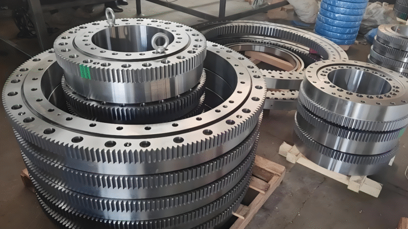
III. MOLD RENEWAL CORE
![图片[1]-模具工厂CNC加工编程工艺与标准-大连富泓机械有限公司](/wp-content/uploads/2026/02/1771582973332_7.png)
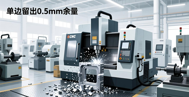
When roughing, 0.5mm allowance should be left on one side for machining to the bottom of the mould frame inserts, in the use of roughing convex CORE, the bottom of the straight position should be left 10mm, its purpose is for the operator to check the roughing condition, to see whether there is a phenomenon of looseness, for the need to harden the shaped convex CORE, the bottom of the straight body of the same stay 10mm, which is for the quenching of the post-finish machining This is for finishing after quenching.
All the glue position, in the finishing operation, to leave 0.02mm such size, but ah, if there are special requirements, that is another situation. For the insertion through the touch through the position, to leave the size of the range of positive 0.02 to 0mm.
3. The convex CORE profile is finished, and the programmer turns on the compensation when doing the light cutter programme, leaving a margin of 0.02mm on one side, while the operator measures the tolerance based on the dimensions of the drawing, which ranges from 0 to -0.005mm on one side, in order to facilitate the assembly process.
4. There are moulded inserts with irregular shapes that are convex CORE, for which details of centring are given in a later section.
IV. Rows and inserts
At the moment of receiving the workpiece, the programmer needs to measure the external dimensions of the workpiece, so as to prevent the problems related to the centring and one-sided touch counting, and the programmer, based on the shape of the workpiece, should discuss with the operation team, so as to adopt a prudent and stable clamping method and touch counting method, the specific details of which are presented in the following section.
2. The row position exists and has a matching position with the front and rear mould nuts, this matching position of the row position needs to leave an extra margin of 0.02mm for FIT.
3. Leave 0.02mm on one side for all glue positions (except for special requirements).
V. Slanted roof
Based on the shape of the workpiece, we discuss with the operation team to adopt a reliable clamping method and a touch counting method, and make it clear that 0.02mm should be left on one side of all the gluing positions (except for special requirements).
VI. Mould blank processing
1. Mould embryo
(1) The base character (chamfer) marked in the drawing of the mould blank should be consistent with the datum on the mould blank, and in order to prevent misunderstanding and confusion in processing, the datum edge should be oriented in the direction of itself when programming.
Firstly, all templates are machined and positioned, then the centre of the guide pillar hole is centred near the reference angle as zero, and finally, the machining coordinates are established accordingly.
First of all, (3) the Z value of the number of touches here is defined as follows, all the templates for forward and reverse machining, all the bottom of the dieblock number of touches as the zero position, for the special requirements of the workpiece, the programmer must be with the relevant personnel to make the situation clear, clear, and in the program list to clearly indicate the zero position of the dieblock position.
2. Board A
For the finishing of the mould frame, when the bottom of the mould frame is processed in the program, the dimensions should be made accurate according to the dimensions of the drawings, the CNC operator uses the calibration table to measure the number according to the tolerance of the drawings, where the tolerance is plus 0.01 to plus 0.02 mm, when the finishing program is carried out on the edge of the frame, it is necessary to turn on the compensation and leave an allowance of 0.02 mm on one side, during the process, the operator uses a block gauge according to the dimensions of the drawings to closely cooperate, the tolerance should be ensured to be within the range of 0.02 to 0.01 mm on one side. Tolerances are guaranteed to be within 0.02 to 0.01 mm on one side.
(2) The side locking position is based on the figure size at the bottom to make the exact size value, the side of the block gauge close fit, the tolerance to ensure that in the unilateral positive zero point zero point 15 to negative zero point zero one millimetre within the range.
(3) The bottom of the insert groove is to be dimensioned accurately and the sides are to be tested for a tight fit using a block gauge to ensure that the tolerances are within the range of 0.015 to 0.01 mm on one side plus 0.01 mm.
(4) Shovelling other dimensions such as the chicken groove, etc., according to the drawing processing of the number of accurate dimensions.
3. Board B
Operation of the mould frame for finishing, first through the procedure of the bottom of the mould frame processing, so that it meets the exact size value, after the CNC operator according to the drawing tolerance, the use of the table to measure the data, the tolerance range is +0.01 0mm, and then carry out the finishing of the frame edge, the program should be turned on to compensate for the unilateral margin of 0.02mm, the operator based on the size of the drawing, the need to use a block gauge for the Tight fit, to ensure that the tolerance is within the range of -0.02 ~ 0.01mm on one side.
(2) The depth of the bottom of the slot of the mould frame line position (Z value), according to the drawing size processing to the exact value, the operator according to the drawing tolerance using the calibration table measurement counting, the tolerance is in the +0.01 to +0.02mm between the side of the program needs to be opened to compensate for the side of the single side of the 0.02mm left to go to the test fit, the operator to use the block gauge to closely match the tolerance to ensure that in the single side of the +0.015 to +0.01mm within the tolerance. Tolerance should be ensured within +0.015 to +0.01mm on one side.
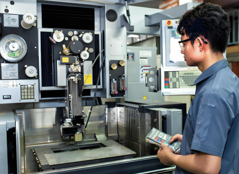
4. Thimble panel:
![图片[2]-模具工厂CNC加工编程工艺与标准-大连富泓机械有限公司](/wp-content/uploads/2026/02/1771582973332_16.png)
When deep machining the position of the ejector pin countersink, the depth is gong to be 0.02mm deeper and the operator measures the number with the help of a micrometer card with a tolerance of 0.02 to 0.01mm, and the side of the ejector pin countersink position is to be machined to size.
(2) The machining dimensions of the part of the base of the slanting top used for assembly are taken as the exact dimensions of the bottom of the ejector pin panel during the machining programme, and the operator uses a comparative table to measure the data, and the machining dimensions of the sides meet the corresponding requirements.
(3) Other positions are machined to the exact dimensions of the 3D drawing.
5. Thimble base plate:
The operator has to use a block gauge for the position of dimensions required for assembly of inserts, and other positions are processed according to the dimensions of 3D drawings to make accurate dimensions.
(2) C plate, according to the 3D drawing size to get quasi-size yo, through the operation of the gong machine group, in accordance with the positive direction of the A code to select the processing surface, and then determine the processing direction, and then gong out of the mould number and the word code it.
(3) Nameplates: need to be engraved in accordance with the requirements of the 3D drawings.
(4) the upper fixed plate, ki-tsui position there are assembly requirements of the size, this size needs to be in the bottom of the upper fixed plate through the process to gong accurate, the operator should use the calibrated table for measurement, and the side of the processing needs to be opened when the compensation, the program should be left unilateral 0.02mm, the operator to use the needle gauge with a tight fit to ensure that in the unilateral +0.015~+0.01mm range, and other dimensions in accordance with the 3D charts. The other dimensions are processed according to the 3D drawing.
The lower fixing plate, for those dimensions where there is a requirement for assembly of inserts, the bottom of the plate should be machined so that it is dimensionally correct and the sides should be tightened with a block gauge, while the other dimensions should be machined in accordance with the 3D drawings and dimensionally correct data should be produced.
VII. Programming:
1. The definition of the coordinates of the steel material for machining is such that the rectangular datum is towards the direction of the person, the square datum is towards the direction of the lower right corner, under normal circumstances, all the steel material is programmed to X, Y as 0, Z value against the bottom of the 0 to establish the machining coordinates, (related content can be viewed)CNC machining(Coordinate definition and clamping direction standard Figures 1, 2 and 3).
For roughing procedures, leave 0.5 mm on one side, and for die nuts that need to be hardened, leave a process table at the top. The reason for this is that this makes it easier to clamp when finishing operations are carried out.
First of all, when finishing, the bottom of the die nut should be gonged, and the front of the die nut, PL, and the glue bit should be avoided to be smashed.
First of all, the mould kernel tube position, all the front and rear mould kernel, in this tube position programming, single side are made small 0.01mm.
5. When machining a flat PL, the programmed machining is based on the dimensions of the drawing to make the dimensions accurate, and the operator has to use a calibration table to measure the data to ensure that the tolerance is within the range of plus zero point zero one to zero millimetre.
6. When machining the curved plane PL, the programmer should make a test program, clearly and explicitly mark the PL of the bottom plane on the programme sheet, and the machining program for the light cutter should be carefully and accurately made to the correct size.
When the front mould kernel machining coordinates are defined, the rectangular datum is towards the person, the square datum is towards the lower right corner, the X and Y four sides are divided in the middle as 0, and the Z touches the bottom as 0 as shown in Fig. 1, and as shown in Fig. 2, and as shown in Fig. 3:
The convex CORE touches are shown in Figures 4 and 5;
The number of row seat touches is shown in Figure 6:
The number of moulded embryo touches is shown in Fig. 7:


No comments