
In reality, many companies in order to save a lot of cost, a large number of homemade single-edged boring tool to carry out processing, for this situation to be analysed, pointing out the shortcomings of the single-edged cutting, based on the actual processing of the accumulated experience, to create a multi-edged boring disc, so that the processing efficiency has been improved, the cost of manufacturing can be saved.
There is a kind of tool used for multi-cutter cutting rough boring bore, it is called boring cutter disc, boring cutter disc is by 4 to 8 machine clamping boring cutter, symmetrically mounted in the cutter slot of the cutter disc, and then through the hexagonal bolts screwed on the cutter disc, two rectangular plate with serrated adjusting teeth, respectively, are fixed in the bottom surface of the cutter body and the cutter disc, when the two upper and lower adjusting plate each staggered tooth, the machining diameter will be a difference of 1 mm. installed. All the cutting edges of the boring tool are in the same plane in the axial direction, the inclination angle of the edge is 0°, the machining radius is exactly the same size, and the adjusting radius can be up to 20mm. the structure of this cutter disc is extremely simple, its cutting is very smooth, it's very convenient to adjust, it's easy to reach the manufacturing side, the cost is extremely low, and it's machining efficiency is higher than the single cutter by more than 10 times.
1、Defects of single cutter cutting boring bar
Large forgings for processing, the removal of the amount are very large, there are some cases even more than 100mm, rough machining time required often accounted for the total machining time of about 70%. Especially in the boring machine for rough boring operation of the bore, consumed by the working hours even to account for the entire boring time of 80% to 90%. boring machine in rough boring processing efficiency is very low. The efficiency of the boring machine in rough boring is very low, this is because in the boring belongs to a single cutter cutting, cutting edge is a large angle of inclination as well as the shank is thin and long, and other factors overlap in the condition of the vibration triggered.
Most of the boring bars used in boring machines have a groove in the middle of the bar, which causes the cutting edge to be off-centre, as shown in Figure 1. There are three defects in this type of bar, first, the tool is unilateral cutting, because the cutting force is concentrated on one side and thus cause vibration; second, the tool's cutting edge inclination angle is relatively large, but the chip space is relatively small, in the formation of chips, will be subjected to the wall of the hole by the extrusion and collision, which causes vibration; third, with the hole diameter gradually become larger and larger, the tip of the cutter with the centre of the bar distance is getting farther and farther away, and the toolbar is thin and long, not rigid enough, thus causing vibration. Thirdly, as the bore diameter gets bigger, the distance between the tool tip and the centre of the boring bar gets farther and farther, and the bar is thin and long, the rigidity is not enough to cause vibration. In this case, can only go to reduce the cutting speed, reduce the depth of the feed, reduce the amount of tool travel.
(a) Vibration and deviation due to unilateral cutting. (b) Vibration and deviation due to forward movement of the tool.
Figure 1 Cutting edge off centre line
In the case of motor power is the same, in the boring bar diameter and length of the same conditions, in the processing of the same workpiece hole conditions, boring machine rough boring cutting speed, but also less than one half of the lathe, and, the depth of its feed, as well as the amount of tooling, are significantly smaller than the lathe. Therefore, the boring machine to provide a cutting does not produce vibration, and processing efficiency of the boring tool, which is rough boring urgently need to solve the problem.
2、 Characteristics of Boring Disc
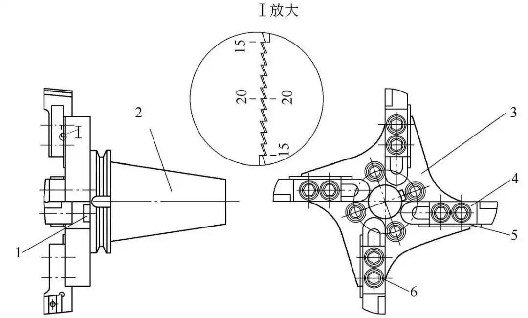
Inspired by the use of multiple cutters on milling discs for rough boring bores, the milling discs can be used as efficient cutting boring discs with a few minor modifications (see Figure 2). The boring disc consists of the cutter plate, a right-handed machine-clamped boring cutter, a serrated adjusting plate, a taper shank, a hexagon socket head cap screw and a square nut.
![图片[1]-切削镗杆加工工序-大连富泓机械有限公司](/wp-content/uploads/2026/02/1771672506897_2.webp)
Fig. 2 Boring disc
1-Square Nut 2-Taper Shank 3-Tool Holder 4-Right Offset Clamping Boring Tools
5 - Serrated adjusting plate 6 - Hexagon socket head fastening bolts
There are four 55 mm by 20 mm by 6 mm open waist-shaped grooves, these waist-shaped grooves are uniformly distributed in the left end of the disc (see Figure 3) and show a distribution of the state of the waist-shaped grooves in the centre line of the disc, and in the waist-shaped grooves will be machined out of a 38 mm by 11 mm waist-shaped through-hole and another processing situation, the other side of the disc is also the back side of the disc to be machined four 53 mm by 18 by 6 mm open waist-shaped grooves, this groove and another waist-shaped through-hole in the same plane with the centre line of the left end of the open waist-shaped grooves. The other side of the cutter plate, that is, the back of the cutter plate is to be machined with four 53 mm by 18 by 6 mm open waist-shaped grooves, the centre line of this groove and the other waist-shaped through-hole and the centre line of the waist-shaped grooves at the left end face are in the same plane, and there is a chip removal notch machined on the top of the waist-shaped grooves, and the right end of the cutter plate is connected to the taper shank.
Figure 3 Cutting disc
The right offset machine clamped boring cutter with an overall cutter body length of sixty millimetres, the type shown in Figure 4, has a forty millimetre by twenty millimetre by twenty millimetre rectangular shank, with two through holes of ten point five millimetres in diameter machined in the middle of the front and back of the cutter shank, which are eighteen millimetres apart, and two countersinks of seventeen millimetres in diameter and ten millimetres in depth machined in the front of the through holes. There are two M ten socket head cap screws that go through the cutter body through holes, then through the cutter disc waist through holes, and then couple with the M ten rectangular nut located in the open waist groove on the back of the cutter disc, thus tightening the boring cutter into the open waist groove at the left end of the cutter disc at a depth of six millimetres. There is a small clearance dynamic fit between the cutter and the slot. Once fitted, the cutting edges of the bores have an inclination of 0° and all the cutting edges of the boring cutters are in the same plane in the axial direction, while the associated machined radii are of the same size.
![图片[2]-切削镗杆加工工序-大连富泓机械有限公司](/wp-content/uploads/2026/02/1771672506897_5.webp)
Figure 4 Right Offset Clamping Boring Tools
Serrated adjustment plate, see Figure 5, it is, is composed of two rectangular plate, one is 50mm × 10mm × 3mm, the other is 50mm × 2mm × 3mm, these two have a serrated adjustment teeth, its teeth are right-angled triangles, the size of the 0.5mm × 0.2mm. 4 groups of such a serrated adjustment plate, the use of wire cutting at the same time, so that we can ensure that the dimensions are exactly the same. 4 sets of these serrated plates are processed simultaneously by wire cutting, so as to ensure that the dimensions are identical. The adjustment plates are fixed to the bottom of the cutter body and to the left side of the cutter disc next to the open waist groove to ensure that when each set of plates is aligned at the 0-percentage mark, the four tips are machined to the same radius. Adjustment means that every time the top and bottom plates are staggered by one tooth, there is a 1mm difference in machining diameter, and adjustment is possible up to a diameter of 40mm.
Figure 5 Serrated Adjustment Plate
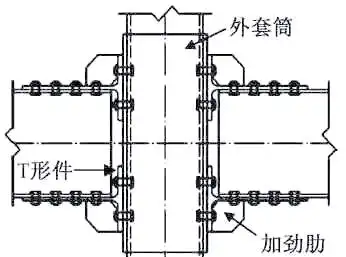
Used for processing larger diameter bore boring disc, can be processed into the shape shown in Figure 6, this disc in addition to the installation of 8 boring tool, and the disc external dimensions are larger, and its two end face opening waist-shaped groove, waist-shaped through-hole, and boring tool size, and the same as the 4-tool head boring disc, the boring disc for larger diameter bore processing, the processing efficiency is twice as much as the 4-tool head boring tool.
Boring cutter plate for machining smaller diameter holes is presented in Figure 7, the left end face of the cutter plate in the form of uniformly processed 4 open waist-shaped grooves, the size of the groove is 25mm × 16mm × 6mm, the waist-shaped grooves of the centre line from the cutter plate centre line of 8mm, in these waist-shaped grooves within the waist-shaped holes to be processed out of a 10mm × 11mm waist-shaped through holes, the cutter plate back to the back of the cutter plate is also processed 4 23mm × 15mm × 6mm open waist-shaped grooves, the back and the shank with taper shank connected to the cutter bar. ×The back of the disc is machined with four 23mm x 15mm x 6mm open waist-shaped grooves, and the back of the disc is connected to the toolholder with a taper shank. The insert is operated with a short shank right offset clamping boring cutter (as shown in Fig. 8), the total length of the cutter body is 33mm, and the shank is a rectangular shape of 18mm×16mm×20mm, and a φ10.5mm through-hole is machined in the middle of the front and back of the cutter shank, and a countersink of φ17mm×10mm is machined in the front of the through-hole, and the boring cutter is securely mounted with the help of an M10 socket head cap screw. With the help of M10 hexagonal bolts, the boring tool is firmly screwed into the waist-shaped groove at the left end of the cutter disc. The cutting edges of all the installed boring cutters are in the same axial plane with the same machining radius size, and the inclination of the boring cutting edge is 0°.
![图片[3]-切削镗杆加工工序-大连富泓机械有限公司](/wp-content/uploads/2026/02/1771672506897_7.webp)
![图片[4]-切削镗杆加工工序-大连富泓机械有限公司](/wp-content/uploads/2026/02/1771672506897_8.png)
Figure 6 Boring disc for machining larger diameter bores
![图片[5]-切削镗杆加工工序-大连富泓机械有限公司](/wp-content/uploads/2026/02/1771672506897_9.webp)
Figure 7 Boring disc for machining smaller diameter bores
Fig. 8 Right Offset Clamping Boring Tools with Short Shanks
The adjusting plate is serrated and it is two rectangular plates, one with dimensions of 25mm x 10mm x 3mm and the other with dimensions of 25mm x 2mm x 3mm, and both rectangular plates have serrated adjusting teeth with an adjusting diameter of 20mm.
3. Processing effect
The use of 4 to 8 boring tool boring disc to bore, the processing of all cutting edges cut together, the cutter head is symmetrically distributed, the radial cutting force is exactly the same, and the direction of the reverse, the upper and lower, left and right offset each other. Ordinary boring tool large edge inclination, cutting force concentrated on one side, the lack of rigidity of the boring bar and chip removal defects to overcome, vibration is eliminated, the cutting speed can be increased by 1 to 2 times, the amount of tooling can be increased by 50%, machining efficiency can be increased by more than 10 times. The cutting speed can be increased by 1 to 2 times, the cutting volume can be increased by 50%, and the machining efficiency can be increased by more than 10 times. Adjusting the machining radius with the serrated adjusting plate is faster, easier and more accurate.
The same specifications of the boring disc can be configured to use two, when using a disc for boring operations, the other disc can be adjusted to the diameter of the next cut in the position, until the previous cut is processed, you can immediately replace the already adjusted disc to continue processing. In this way, the non-processing time can be minimised and the processing efficiency can be improved.
When roughing the bore, the boring disc's machining efficiency is two to four times that of an imported double-tool boring tool, yet its manufacturing cost is only about one-half that of a double-tool boring tool, so its cost-effectiveness is far greater than that of a double-tool boring tool.
With extremely simple structure, good rigidity, high strength, smooth cutting, convenient adjustment, manufacturing is not difficult, low-cost characteristics of the boring disc, can be used in the boring machine, but also in the taper shank into a square shank can be used in the lathe, as well as the gantry milling machine for use.


No comments