
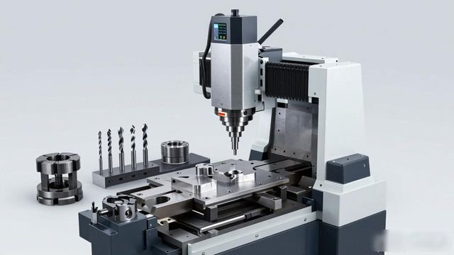
The present utility model relates toMill-Turn Machining CentreIn technical terms, specifically, it is a worktable for milling operations used in turning-milling machining centres.
Background technology:
Composite machining is one of the most popular machining processes in the field of mechanical engineering at present. It is classified as an advanced manufacturing technology, and refers to the integration of several different machining processes on a single machine tool. Composite machining has the widest range of applications and is extremely challenging; Notably, turning-milling composite machining involves the integration of a CNC lathe and a machining centre within a single machine tool.
A search has revealed that there is a type of CNC turning-milling centre, the patent publication number of which is [...]. It comprises a lathe bed, a sheet metal housing, and a spindle unit, as well as a Z-axis guideway structure and an X-axis guideway structure. On the upper surface of the X-axis guideway structure, a turning-milling composite power head serving as the Y-axis is mounted vertically, whilst a central support frame is fixedly connected to one side of the Z-axis guideway structure. Through the interaction of the Z-axis guide structure, the X-axis guide structure and the turning-milling composite power head acting as the Y-axis—all of which move relative to one another to achieve 3-axis interpolation—and utilising the spindle of the spindle unit along with the rotating cutting tools of the turning-milling composite power head, multi-spindle machining is achieved, allowing the workpiece to undergo turning, milling, grinding and drilling operations after being clamped just once.
Among existing technologies, there are drawbacks and shortcomings associated with the use of turning-milling centres for machining workpieces on milling tables. When a turning-milling centre is used to machine workpieces on a milling table, multiple cutting tools are required; after each tool change, the tool must be re-aligned, which wastes a significant amount of time and makes tool changes inconvenient.
Technology Enabling Elements:
The objective of this utility model is to provide a milling table suitable for turning-milling composite machining centres, which offers the advantage of facilitating tool changes whilst also saving a significant amount of tool setting time. It addresses the issue encountered with milling tables used in turning-milling composite machining centres where multiple tools are required during machining, where, after each tool change, re-tooling is required, which wastes a great deal of time and makes tool changing extremely inconvenient.
A milling table for use in a turning-milling machining centre, designed to achieve the aforementioned objectives, comprises the following components: a protective cover, a mounting plate, the table body, and a support plate. Several support legs are welded to the underside of the worktable body. The protective cover is fitted over the top surface of the worktable body, and a mounting bracket is fixed inside the cover near the top. The first connecting plate is fixed to the underside of the mounting bracket. The fixing plate is connected to the underside of the first connecting plate via a pivot, and buffer outer rods are welded to the underside of the fixing plate. The inner buffer rod is welded to the corresponding upper surface of the support plate, and this inner buffer rod is inserted into the outer buffer rod. Furthermore, a spring is wound around the outer surface of the inner buffer rod. A support rod is mounted and secured to the underside of the support plate, and a blade holder is inserted into the interior of the support rod.
In the preferred embodiment, the lower surface of the tool holder is connected to the cutting head by means of a threaded connection, and the interior of the tool holder and the support rod are likewise connected by means of a threaded connection to a bolt, whilst the outer ends of the bolt on both sides are connected to nuts by means of threaded connections.
More preferably, the underside of the fixing plate is provided with a fixing rod, and this fixing rod is connected to the support plate.
A preferable option is for the fixing plate to have a through-hole formed in it, with the interior of this through-hole connected to the first locking valve by means of a thread.
In this particular design, there are a total of four support legs, which are arranged in a rectangular pattern around the underside of the workbench.
Preferably, the upper surface of the workbench body is provided with a sliding plate connected in a sliding manner, and a fixed clamping device is provided on one outer end face of the sliding plate; the upper surface of the sliding plate is provided with a fixed second connecting plate, and a second locking valve connected by a threaded connection is provided on the upper surface of the second connecting plate.
Compared with the prior art, the present utility model offers the following advantages: by incorporating a mounting frame, a fixing plate, a tool holder, a support plate, an outer buffer rod, a spring and an inner buffer rod, the present utility model facilitates the replacement of cutting tools whilst significantly reducing tool setting time. By loosening the second locking valve, adjust the position of the sliding plate according to the workpiece being machined; the fixture can then secure the workpiece; tighten the second locking valve; mount the cutting heads inside the tool holder via a threaded connection; select an appropriate number of cutting heads to be installed inside the tool holder according to specific requirements; insert the tool holder into the support rod, thread the bolt through the tool holder and support rod, and tighten the nut to secure the tool holder. During machining, if you need to switch to a different cutting head, loosen the first locking valve, rotate the support plate to bring the other cutting head into position, no re-tooling is required; simply tighten the first locking valve. During machining, when the cutting head is subjected to vibration, it presses against the tool holder, which in turn presses against the support plate; the support plate then presses against the internal buffer rod, and the internal buffer rod presses against the spring; The spring absorbs the vibration. As the support plate and the fixed plate are already secured by the fixing rod, no additional vibration is generated by the spring, making it more convenient to use and offering greater practicality.
illustrate
Figure 1 is a schematic diagram showing the front view of the present utility model;
Figure 2 is a schematic diagram showing an enlarged view of component a of the present utility model;
Figure 3 shows a top view schematic diagram of the support plate of the present utility model.
In the figure: a protective cover, a first locking valve, a fixing plate, a pivot shaft, a mounting bracket, a fixing rod, a first connecting plate, a tool holder, a support rod, a cutting head, a worktable body, support legs, a second connecting plate, a slide plate, bolts, a nut, a support plate, a clamp, a second locking valve, an outer buffer rod, a spring, and an inner buffer rod.
practical way of doing sth.

The technical solutions of the embodiments of the present utility model will be described clearly and completely below with reference to the accompanying drawings. It is evident that the embodiments described are merely some of the embodiments of the present utility model and do not constitute all of them. All other embodiments obtained by a person skilled in the art based on the embodiments of the present utility model, without the need for creative work, fall within the scope of protection of the present utility model.
In the description of the present utility model, it should be noted that the directions or positional relationships indicated by terms such as “upper”, “lower”, “inner”, “outer”, “front end”, “rear end”, “both ends”, “one end” and “the other end” are based on the orientation or positional relationships shown in the accompanying drawings and are intended solely to facilitate the description of the present utility model and to simplify the description; they do not indicate or imply that the apparatus or components involved must necessarily have a specific orientation, be constructed in accordance with a specific orientation, or be operated in a specific manner. Therefore, they should not be construed as limiting the scope of the present utility model. Furthermore, the terms “first” and “second” are used solely for descriptive purposes and should not be construed as indicating or implying relative importance.
In describing the present utility model, it should be clarified that, unless otherwise clearly and explicitly stipulated or defined, terms such as “installation”, “provided with” and “connection” should be interpreted in a broad sense. For example, with regard to “connection”, this may refer to a fixed connection, a detachable connection, or an integral connection; it may be a mechanical connection or an electrical connection; It may be a direct connection, an indirect connection achieved through an intermediate medium, or an internal connection between two components. A person skilled in the art will be able to understand the specific meaning of the above terms in the context of the present utility model based on the specific circumstances.
Please refer to Figures 1 to 3. The present utility model provides an embodiment: a milling table for a turning-milling composite machining centre, comprising a protective cover 1, a fixing plate 3, a worktable body 11 and a support plate 17. Four support legs 12 are welded to the underside of the worktable body 11, arranged in a rectangular array on the underside of the worktable body 11, The protective cover 1 is fitted over the upper surface of the worktable body 11, and a mounting frame 5 is fixed to the inner top of the protective cover 1; a first connecting plate 7 is fixed to the lower surface of the mounting frame 5.
The outer buffer rod 20 is welded to the underside of the fixed plate 3, and the inner buffer rod 22 is welded to the upper surface of the support plate 17; the inner buffer rod 22 is inserted into the outer buffer rod 20, Spring 21 is wound around the outer surface of buffer inner rod 22; fixing rod 6 is secured to the underside of fixing plate 3; fixing rod 6 is connected to support plate 17; when cutting head 10 is in operation, cutting head 10 is subjected to vibration; cutting head 10 presses against tool holder 8; the tool holder 8 presses against the support plate 17, the support plate 17 presses against the inner buffer rod 22, and the inner buffer rod 22 compresses the spring 21, Spring 21 is capable of absorbing the vibrations. As support plate 17 and fixing plate 3 are already secured by fixing rod 6, no additional vibrations are generated by spring 21, making it more convenient to use and offering greater practicality.
There is a fixed plate 3, which is pivotally connected to the underside of the first connecting plate 7 via a pivot pin 4. A through-hole is formed in the fixed plate 3, and the first locking valve 2 is threadedly connected within this through-hole. A support rod 9 is fixed to the underside of the support plate 17, and a tool holder 8 is inserted into the support rod 9; The lower surface of the blade holder 8 is threadedly connected to the blade head 10, and a bolt 15 is threadedly connected within both the blade holder 8 and the support rod 9; both outer ends of the bolt 15 are threadedly connected to nuts 16. The cutting head 10 may first be screwed into the tool holder 8; then, depending on specific requirements, a suitable number of cutting heads 10 may be selected and installed within the tool holder 8; next, the tool holder 8 is inserted into the support rod 9; subsequently, the bolt 15 is screwed into the tool holder 8 and the support rod 9; and tighten nut 16 to secure the tool holder 8 in place. During machining, if it is necessary to change to a different cutting head 10, simply loosen the first locking valve 2, rotate the support plate 17, and align the other cutting head 10 with the square. There is no need to re-align the tool; simply tighten the first locking valve 2. This makes the tool more convenient to use and significantly enhances its practicality.
The upper surface of the main body 11 of the work platform is slidably connected to the slide plate 14, and the outer end face of one side of the slide plate 14 is fixed to the clamping device 18, the top surface of the sliding plate 14 is secured to a second connecting plate 13, and the top surface of the second connecting plate 13 is threadedly connected to a second locking valve 19, If the second locking valve 19 is loosened, the workpiece can be secured by the clamping device 18 by sliding the slide plate 14 to the appropriate position for machining; if the second locking valve 19 is tightened, the device becomes more convenient to use and offers greater practicality.
First, let us explain the operating principle: loosen the second locking valve 19 to proceed with the subsequent operations. Depending on the position of the sliding plate 14 relative to the workpiece, the fixture 18 can secure the workpiece. Then, tighten the second locking valve 19. Next, screw the cutting head 10 into the tool holder 8. Select the appropriate number of cutting heads 10 to install inside the tool holder 8 according to specific requirements, then insert the tool holder 8 into the support rod 9, and thread the bolt 15 through the tool holder 8 and support rod 9, Tighten nut 16 to secure the tool holder 8. During machining, if a different cutting head 10 is required, loosen the first locking valve 2, rotate the support plate 17 to position another cutting head 10 in the correct orientation, without the need for re-tooling, Tighten the first locking valve 2. Finally, during machining, the cutting head 10 is subjected to vibration; the cutting head 10 presses against the tool holder 8, the tool holder 8 presses against the support plate 17, and the support plate 17 presses against the buffer inner rod 22, the buffer inner rod 22 presses against the spring 21, and the spring 21 absorbs the vibration. As the support plate 17 and the fixed plate 3 are secured by the fixing rod 6, no additional vibration is generated by the spring 21.
It will be apparent to those skilled in the art that the present utility model is not limited to the details of the illustrative embodiments described above, and that the present utility model may be realised in other specific forms without departing from the spirit of the present utility model or contravening its essential features. Therefore, from every perspective, the embodiments should be regarded as illustrative in nature and not limiting. The scope of the utility model is defined by the appended claims rather than by the foregoing description; consequently, it is intended that all variations falling within the meaning and scope of the equivalent elements of the claims be included within the utility model. No reference to any figure in the claims shall be construed as limiting the claims to which it relates.
 Chinese
  Japanese
  English
  German
  Finnish
Leave a Reply
You must be logged in to post a comment.