
wire erosionAnalysis of Key Process Considerations for Moulds: A Thesis on Electronic Machinery
Analysis of Key Process Points in Wire-Cut Machining of Moulds_Thesis on Electronic Mechanics
This serves as an introduction to wire-cut EDM as the primary machining method for stamping die components; however, conducting a thorough process analysis and accurately calculating the wire path for the electrode in CNC programming are factors that directly affect the machining accuracy of the die. By determining the wire-threading holes and optimising the cutting paths, the cutting process can be improved; this represents a highly effective and crucial approach to enhancing cutting quality and production efficiency.
2. Calculation of the actual trajectory
According to a vast amount of statistical data, the actual dimensions of parts following the wire-cut EDM process are mostly within a range close to the mid-point of the tolerance band (also known as the “mid-point dimension”); therefore, for dimensions with specified tolerances on stamping die component drawings, the mid-dimension should be used as the programming data for the actual cutting path. It is calculated as follows: the mid-dimension equals the base dimension plus (the upper deviation plus the lower deviation).
For example, the outer radius specified in the drawing dimensions is R25–0.04; the corresponding midpoint dimension is 25 plus (0 minus 0.04) divided by 2, which equals 24.98 (mm).
Given the characteristics of wire-cut electrical discharge machining, there is always a discharge gap between the workpiece and the electrode wire, therefore, during the cutting process, a certain distance must be maintained between the theoretical contour of the workpiece—that is, the drawing—and the actual trajectory of the electrode wire. This distance is the perpendicular distance between the centreline of the electrode wire’s trajectory and the workpiece contour; it is referred to as the offset f₀, also known as the compensation value, which is as follows.
f0 = R (wire) + δ (electric)
In the equation, R_wire denotes the radius of the electrode wire.
δ-discharge — single-sided discharge gap
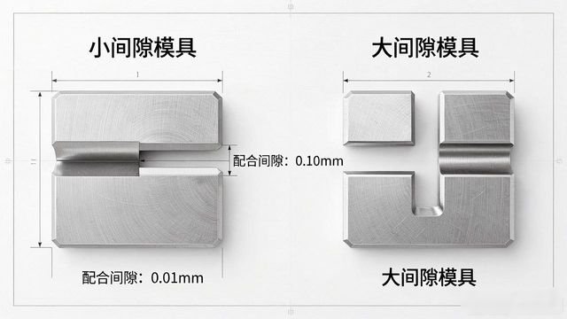
When performing wire-cut EDM machining on the punch and die of a stamping die, it is necessary to take into account the radius of the electrode wire (R), the single-sided discharge gap (δ), and the single-sided fitting clearance between the punch and die (δ配), in order to determine a reasonable clearance compensation value (f0).
For example, when machining a punching die—that is, to ensure the punched dimensions of the workpiece meet the requirements—the punching punch is used as the reference. Therefore, the clearance compensation value for the punch is calculated as follows: f punch equals R thread plus δ electric; the dimensions of the die should be increased by δ fit. Next, for the machining of blanking dies—where the aim is to ensure the dimensions of the blanked workpiece—the blanking die is taken as the reference. The clearance compensation value for the die, f_die, is equal to R_wire plus δ_EDM, whilst the punch dimensions should be increased by δ_fit. Please refer to Figure 1. The machining accuracy and surface quality of wire-cut EDM are directly affected by the magnitude of the offset. If the offset is too large, the gap will be excessive, causing the electrical discharge to become unstable, which in turn affects dimensional accuracy; conversely, if the offset is too small, the gap will be too narrow, which will affect the finishing allowance. When re-cutting is required, the electrical parameters will gradually weaken; non-electrical parameters must also be adjusted accordingly to improve machining quality. This includes the gap compensation values for the punch and die shown in Figure 1.
(a) Punch (b) Die

Based on practical experience, when machining blanking dies using wire-cut EDM, the clearance should be slightly smaller than that of the so-called “large-clearance” blanking dies commonly used internationally (the values recommended in the *Manual*). This is because, during wire-cut machining of the punch and die, a brittle and loose molten layer forms on the surface of the workpiece; the higher the electrical parameters, the poorer the surface finish and the thicker the molten layer. Furthermore, as the number of punching operations increases, this brittle, loose surface layer is gradually worn away, causing the clearance between the die and punch to gradually increase, thereby meeting the requirements for a “large” clearance.
3. Determining the threading holes
The position of the wire-threading hole is of paramount importance in terms of machining accuracy and cutting speed. Generally speaking, the most ideal position for the wire-passing hole is at the intersection of known trajectory dimensions, or at a coordinate point that facilitates calculation. The aim is to simplify the calculation of coordinate dimensions during the programming process, thereby reducing errors. When cutting a die workpiece with a closed-type hole, the wire-entry hole should be positioned at the centre of the shaped hole; this allows for both precise machining of the wire-entry hole and convenient control of the coordinate path calculations, although the unnecessary entry stroke is relatively long. For the cutting of large-sized profile holes, the wire-passing hole may be positioned at a corner close to the machining path to minimise the unnecessary travel. When cutting the outline of a punch, the wire-feeding hole should be positioned outside the contour, preferably near the starting point of the cut. When cutting narrow slots, the wire-feeding hole should be positioned at the widest part of the shape; the wire-feeding hole must not intersect with the cutting path. Furthermore, when cutting two or more workpieces from the same blank, separate threading holes must be provided for each; a single threading hole must not be used to cut all workpieces in a single operation. When cutting large punches, where conditions permit, several thread-passing holes may be positioned along the cutting path so that, should the wire break during cutting, it can be rethreaded at the nearest point and cutting resumed.
The diameter of the thread-passing holes should be appropriate, typically falling within the range of Φ2 mm to Φ8 mm. If the hole diameter is too small, this will not only make drilling more difficult but will also make it less convenient to pass the wire through; if the hole diameter is too large, it will increase the fitter’s workload. Where a large number of small-diameter shaped holes are required, and these holes are arranged in a relatively dense pattern, smaller threading holes—namely, those between Φ0.3 mm and Φ0.5 mm—should be used to prevent the individual threading holes from intersecting or interfering with one another.
Whether the cutting path is appropriate or not will determine the extent of the workpiece’s deformation.
It is evident that optimising the cutting path helps to improve cutting quality and reduce machining time. The planning of the cutting path should ensure that the workpiece remains within the same coordinate system as the clamping support throughout the machining process, thereby preventing the effects of stress-induced deformation, and should adhere to the following principles.
(1) In most cases, it is advisable to position the start of the cut close to the clamped end, to place the section of the cut that separates the workpiece from the clamped portion at the very end of the cutting path, and to set the pause point at the position adjacent to the clamped end of the blank.
(2) The starting point of the cutting path must be selected at a location where the workpiece surface tends to be relatively flat and where the impact on machining performance is minimal. For workpieces with high precision requirements, it is best practice to select the cutting starting point within a pre-drilled thread-passing hole on the blank; under no circumstances should the cut be initiated directly from the exterior of the blank, as this would cause deformation at the point where the workpiece is cut.
(3) To minimise deformation of the workpiece, one approach is to ensure that the cutting path remains at a certain distance from the outline of the blank; this distance is typically defined as no less than 5 mm.
When carrying out wire-cut machining, particular attention must be paid to optimising the cutting path in order to meet certain specific process requirements.
(1) For parts with complex concave cavities, where wall thickness or cross-sectional dimensions vary significantly, a two-pass (or multi-pass) cutting method is recommended to minimise deformation and ensure machining accuracy. Typically, for areas requiring high precision, an allowance of 2 mm to 3 mm is first left for rough cutting; once the workpiece has undergone a significant degree of deformation, fine cutting is then carried out until the required dimensions are achieved. To further improve cutting accuracy, a 0.20 mm to 0.30 mm allowance may be reserved for semi-finish cutting prior to the finish cut; this constitutes the three-pass cutting method, where the first pass is rough cutting, the second is semi-finish cutting, and the third is finish cutting. This is an effective method for enhancing the precision of wire-cut EDM machining for moulds.
(2) Where a workpiece needs to be cut to form a “sharp corner” (i.e. “corner clearance”), one method to achieve this using the sharp-corner cutting technique is Method 1, which involves adding a short section of overcut to the original path, as illustrated by A0 – A1 in Figure 2. The aim is to ensure that the maximum lag point during electrode wire cutting reaches point A0 in the programme, before proceeding to the additional point A1, then returning to point A0, and finally continuing with the original programme; this enables the cutting of a sharp corner. Another method is to adopt the cutting path shown in Method Two in Figure 3, which involves adding a small square or triangular overcut path at the sharp corner as an additional programme segment. This ensures that a sharp corner with clear edges is produced. Figure 2: Sharp Corner Cutting Method; Figure 3: Sharp Corner Cutting Method Two
(3) When performing tangential cutting EDM at corners, the reaction force generated by the electrical discharge causes the actual position of the electrode wire to lag behind its movement along the machine’s X-axis, as well as its movement along the Y-axis, thereby resulting in poor corner accuracy.
If the electrode wire moves with a delay, this will result in the outer arc of the workpiece being undercut during machining, and there will be insufficient machining of the inner arc; this, in turn, will cause a loss of accuracy at the corners of the workpiece. Therefore, for corners where the workpiece requires a high degree of precision, the drive speeds of the X and Y axes should be automatically reduced, thereby ensuring that the actual movement speed of the electrode wire remains synchronised with the X and Y axes. In other words, for machining operations, the higher the precision requirements, the slower the drive speed should be at the corners.
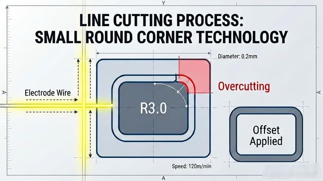
(4) With regard to the small fillet cutting method, if the radius of the internal fillet specified in the drawing is found to be smaller than the offset during cutting, this will result in “undercutting” at the fillet. Therefore, it is essential to ensure that the minimum fillet radius in the drawing’s contour is greater than the offset of the final finishing pass; otherwise, a thinner electrode wire must be selected. During the main cutting and initial finishing passes, different fillet radii can be set for each pass according to the varying offsets, set different internal fillet radii; in other words, different subroutines for internal fillet radii should be programmed for the same section of the contour. The internal fillet radius specified in the subroutine must be greater than the offset for that pass; this allows for the cutting of extremely small fillets and ensures superior fillet cutting quality.
5. Preparation of the workpiece prior to cutting
Prior to cutting, die and punch components must meet certain requirements; these requirements are designed to minimise deformation of the die during the cutting process and to improve the quality of the machined parts.
(1) The parallelism error between the upper and lower surfaces of the workpiece shall be less than 0.05 mm.
(2) A pair of orthogonal vertical faces should be machined on the workpiece to serve as reference surfaces for positioning, alignment and measurement.
(3) Mould cutting should be carried out using an enclosed cutting process to reduce cutting temperatures and minimise deformation.
(4) The amount of material to be left around the edges of the workpiece after cutting should ideally be one-quarter of the thickness of the die; in most cases, the allowance around the edges should be no less than five millimetres.
(5) Minimise mould deformation, select the appropriate machining method, and strictly adhere to heat treatment specifications; for moulds requiring high precision, it is best to carry out two tempering treatments.
(6) All pin holes and screw holes in the workpiece should be machined to the correct shape prior to quenching.
(7) After the die has undergone heat treatment, scale and impurities must be removed from the wire-passing holes to prevent a deterioration in electrical conductivity, which could lead to wire breakage.
(8) Prior to wire cutting, any scale and rust must be removed from the surface of the workpiece, and demagnetisation must also be carried out.
6. Conclusion
Immediately after programming has been completed, and before cutting operations commence, the programme must be carefully checked and thoroughly verified to ensure its accuracy. The CNC systems of wire-cut EDM machines all provide methods for programme verification, the most commonly used of which include: the plot verification method, which is primarily used to verify whether there are any syntax errors in the programme and whether it conforms to the machining contour specified in the drawing; the idle-stroke verification method, which allows the actual machining conditions of the programme to be assessed, checking for potential collisions or interference during the machining process, as well as verifying whether the machine’s travel range meets the relevant machining requirements; and the dynamic simulation verification method, which utilises a simulation of actual dynamic machining to conduct a comprehensive verification of the programme and the machining trajectory. Generally speaking, the programme should be run through in its entirety to check whether the graphics “return to zero”. For punching dies with high dimensional accuracy requirements and minimal clearance between the punch and die, a test cut can first be carried out using thin sheet metal, to verify the relevant dimensional accuracy and clearance. Should any non-conformities be detected, the programme must be corrected promptly; only once verification has been successfully completed may formal cutting operations commence. Once the actual cutting is complete, do not rush to remove the workpiece; check whether the start and end coordinate points are consistent. If any issues are found, take prompt corrective action.
 Chinese
  Japanese
  English
  German
  Finnish
Leave a Reply
You must be logged in to post a comment.