
xxx Company, to carry outWelding Procedure QualificationThe document, subsequently edited, is numbered -Fe1-1-SMAW-12; it was prepared by [Name], reviewed by [Name] and approved by [Name]. The table of contents includes: I. Welding Procedure Qualification Statement (1 page in total); the table of contents further includes: II. Pre-welding Procedure Instruction (2 pages in total); the table of contents further includes: III. Welding Procedure Qualification Report (3 pages in total); and the table of contents also includes: IV. Appendices (Inspection and Material Reports) (5 pages in total). In the Welding Procedure Qualification Specification, the client is xxx Company, the commission reference number is a specific number, the welding position is vertical (3G), the commission date is 20 October 2011, the joint type is a V-groove butt joint, with a specific reference number; the degree of mechanisation is manual; the welding method is SMAW; the shielding gas is /; the applicable standard is NB/; and the required completion date is 4 November 2011. Inspection items include visual inspection, with the inspection standard being visual assessment; there is also a tensile test, with the reference standard at room temperature being GB/T 228; non-destructive testing includes radiography, with the reference standard being JB/; and ultrasonic testing, with the reference standard being //; further including bending tests, with the reference standard for face and back bending being GB//; the reference standard for penetrant testing is //, GB// 2; and the reference standard for magnetic particle testing is //; The reference standard for impact testing of the heat-affected zone of welds is GB//; the reference standard for weld chemistry is GB/T 229; the reference standard for joint hardness is //; the reference standard for ferrite determination is ///; the reference standard for metallographic microstructure is //; and the reference standard for corrosion testing is //. the macroscopic reference includes a schematic diagram of the joint type; the base metal grades are Q235B and Q235B welded together, the thickness is 12 mm, the welding consumable grade is J427, the diameter is 3.2–4.0 mm, the date of preparation is a specific date, the date of review is a specific date, and it is specifically noted that a separate form must be completed for each combination of base metal and welding consumable.
Rewrite as follows: Pre-welding procedure specification, or pWPS; it comprises 2 pages in total; this is page 1; the organisation is xxx Company. The Pre-Welding Procedure Specification has a reference number and is dated 21 October 2011. It is based on a welding procedure qualification report with the reference number /. The welding method is SMAW. Regarding the degree of mechanisation, this is manual welding. As for the joint, the groove type is V-type. For the backing material, it is stated here as (material and specifications): /, and other details are also marked as /. There is also a schematic diagram, which includes the joint type, groove type and dimensions, weld layers, and the arrangement and sequence of weld passes. Regarding the base metal, the category code is Fe1 and the group code is Fe1-1; it is to be welded to base metal with category code Fe1 and group code Fe1-1, or in accordance with standard GB/T 3247. The material designation is Q235B; welding must also be carried out in accordance with standard GB/T 3247 and material designation Q235B. The thickness range of the base metal for butt welds is 12 mm. The thickness range of the base metal for fillet welds is listed as ‘/’. For the pipe diameter and wall thickness ranges, ‘Other’ is specified here for both butt welds and fillet welds. Regarding filler metal, the welding consumable category is FeT1-1. The welding consumable standard is NB/.2. The filler metal dimensions are 3.2 and 4.0 mm. The welding consumable type is E4315. The welding consumable grade, i.e. the metal grade code, is J427. The filler metal category is FeT1-1. Additionally, the weld metal thickness range for butt welds is 12 mm. The weld metal thickness range for fillet welds is entered as /. For the chemical composition of the corrosion-resistant surfacing metal, enter (%): Other. Please note that a separate form must be completed for each combination of base metal and welding material.

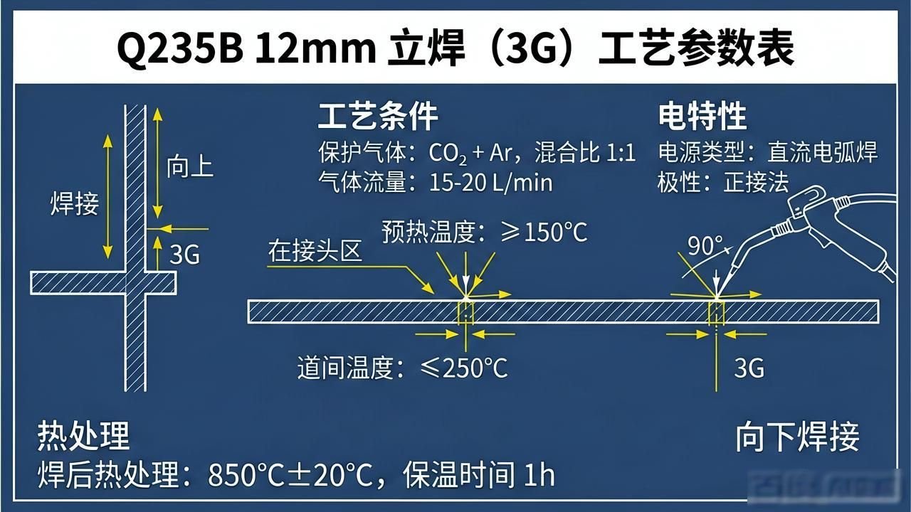
Regarding part of the content on page 2 of a total of 2 pages: the welding position is vertical (3G) at a butt joint; there are two possible directions for vertical welding, namely upwards and downwards. For vertical welding at an upward fillet joint, the welding direction also has two options: upwards and downwards. With regard to post-weld heat treatment, this includes the temperature range, expressed in °C, and the holding time range, expressed in hours. Preheating involves the minimum preheating temperature, expressed in °C, and the maximum interpass temperature, expressed in °C. This is followed by a description of the heating method and details regarding gases, Specific details are provided regarding the types of gas, and the mixing ratios are also mentioned; the flow rate is measured in L/min. Detailed information is provided on shielding gas, with corresponding values specified for end-of-pass shielding gas and relevant data recorded for back-side shielding gas. Regarding electrical characteristics, the current type is specified as direct current, and the polarity is reverse polarity, the welding current range is 110–180 A, the arc voltage range is 22–26 V, and the welding speed range is 6–8 cm/min, the type and diameter of the tungsten electrode, nozzle diameter, type of welding current and wire feed speed are also filled in as required; furthermore, the current and voltage ranges are listed separately according to the welding position and thickness, as detailed in the table below; Different welding parameters apply to different situations regarding weld passes and layers; for example, on the front side, different serial numbers correspond to different reverse polarity welding current ranges, arc voltage ranges and welding speeds, whilst the reverse side also has corresponding parameters for welding methods, filler metal, current and voltage. Technical measures include oscillating welding or non-oscillating welding (with slight oscillation), with specific requirements for oscillation parameters. Pre-welding and interpass cleaning methods involve rust removal using a wire brush, as well as slag removal and cleaning between passes; root cleaning on the reverse side involves carbon arc gouging or grinding with a grinding wheel; single-pass or multi-pass welding refers to single-pass single-wire welding or multi-wire welding, Other relevant welding parameters are also listed as specified, and there are clear requirements regarding information such as the date of compilation, review and approval. On page 1 of the three-page document, the organisation is named as XXX Company and the welding procedure qualification report number is PQR 151 – Fe1 – 1 – SMAW – 12. The pre-welding procedure specification number is PWPS 151 – Fe1 – 1 – SMAW – 12; the welding method is SMAW; the degree of mechanisation is manual; the joint schematic illustrates the groove type, dimensions, backing, and the thickness of the weld metal after each pass; the base metal material standard is GB/T 3247; the material designation is Q235B, the group number is Fe1 – 1, the welding thickness for materials of the same group and grade (Fe1 – 1) is 12 mm, and there are corresponding specifications for diameter and other parameters; regarding post-weld heat treatment, the holding temperature is listed in sequence, with the unit being °C, holding time (in hours), and the shielding gas mixture ratio and flow rate (in L/min), with specific values provided for the shielding gas. Detailed information is provided regarding the shielding gas for the tail section, and the corresponding entries for the back-side shielding gas are also clearly recorded.
 Chinese
  Japanese
  English
  German
  Finnish
Leave a Reply
You must be logged in to post a comment.