
Technical Brief:
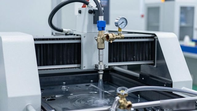
In response to the low efficiency and high costs associated with manual deburring following CNC machining, this patent proposes a high-pressure water deburring methodCleaning device, A high-pressure water system has been installed, complete with nozzles that move in tandem with the spindle. By utilising the impact of high-pressure water, it can automatically remove burrs and eliminate dirt, thereby replacing manual labour, significantly improving cleaning efficiency and enhancing the quality of the clean. At the same time, the use of a filtration and recirculation system reduces water costs.
Keywords: high-pressure water deburring, CNC cleaning system
The field to which this utility model relates is CNC machine tool machining; in particular, it relates to a device intended for use within a CNC machine, which is capable of deburring and cleaning using high-pressure water.
Background technology:
Currently, during the machining process, operators are required to install and clamp the workpieces onto the machining table of the CNC centre on-site, and to remove them once machining is complete. The workpieces must then be cleaned manually and deburred by hand; such operations are highly inefficient, whilst labour costs remain high. Following milling on a CNC (computer numerical control) machine, the workpieces become coated with the cutting fluid used in the machine. This requires staff to remove the workpieces and then clean and blow-dry them, thereby increasing the time taken for the operation and significantly reducing efficiency.
Technology Enabling Elements:
(1) Technical issues to be addressed
The objective of this utility model is to provide a device, namely a high-pressure water deburring and cleaning device for use within a CNC machine, with the aim of addressing the problem of low efficiency associated with existing manual deburring and cleaning methods.
(2) Technical Solution
This utility model provides a high-pressure water deburring and cleaning device for use within a CNC machine, with the aim of resolving the aforementioned technical issues. The device comprises a high-pressure water unit and a spray head; the high-pressure water unit is equipped with a water tank, the inlet of which is connected to a water source via a water pipe, whilst the outlet of the water tank is connected to the inlet of a high-pressure pump via a water pipe, the outlet of the high-pressure pump is connected to the inlet of the spray head via a water pipe; this spray head comprises a rod and a nozzle, with the nozzle securely mounted at the lower end of the rod, whilst the upper end of the rod is fixed to the spindle inside the CNC machine.
Among these components is a filter housing, which contains a mesh that serves to filter the water; the inlet of the filter housing, through which water enters, is connected to the outlet of the filtered water, whilst the outlet of the filter housing is connected to the inlet of the water tank via a water pipe.
In this context, the water pressure at the outlet of the high-pressure pump is 0.8–1.4 MPa.

In this context, a control valve and a pressure gauge are fitted to the pipe connected to the outlet of the high-pressure pump.
In this case, a pressure-boosting pipe is connected to one side of the high-pressure pump.
In this case, the water pressure within the pressure-boosting pipe is 0.8 MPa.
Among these components is a part called the nozzle, which consists of a T-shaped sleeve and a spray needle. The upper end of the sleeve is secured to the lower end of the pull rod. Furthermore, a water reservoir is situated at the lower end of the sleeve. The spray needle, meanwhile, is secured to the lower opening of the water reservoir.
In this case, the upper end of the sleeve is connected to the water inlet of the nozzle.
In this context, the spray needle is provided with a number of water outlets.
In particular, the lower end of the spray needle is tapered.
(3) Beneficial effects
The present utility model provides a high-pressure water deburring and cleaning device for use within a CNC machine. Equipped with a high-pressure water system and nozzles, it utilises the instantaneous impact force of high-pressure water to remove burrs, flash and dirt generated during machining, replacing manual cleaning operations, saving labour, improving cleaning efficiency and resulting in superior cleaning results.
illustrate
Figure 1 is a schematic diagram of the structure of an embodiment of the present utility model;
Figure 2 shows a side view of the nozzle in an embodiment of the present utility model;
Figure 3 shows a sectional view of the nozzle in an embodiment of the present utility model;
Figure 4 shows a schematic diagram of the structure of the nozzle in an embodiment of the present utility model.
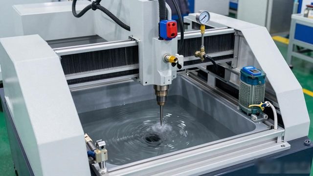
Firstly, in the diagram, there are several components: firstly, the water tank; secondly, the high-pressure pump; thirdly, the pull rod; and fourthly, the nozzle. Next, there is the water pipe; then, the filter housing; followed by the filter screen; and then the regulating valve. followed by the pressure gauge; further down is the pressure-boosting pipe; further down still is the sleeve; next is the spray needle; in addition, there is a water reservoir; furthermore, there is an outlet; there is also an inlet; and finally, there is a mounting plate.
practical way of doing sth.
Below, with reference to the accompanying drawings and examples, a further detailed description of the specific embodiments of the present utility model is provided. The following examples are provided to illustrate the present utility model; however, they are not intended to limit the scope of the present utility model. Punctuation.
There is a device of this kind, which is a high-pressure water deburring and cleaning unit installed within a CNC machine; The scope of the system is illustrated in Figures 1 to 4. It comprises a high-pressure water system and nozzles, with the high-pressure water system consisting of water tank 1 and high-pressure pump 2. The inlet of water tank 1 is connected to a water source via water pipe 5, thereby supplying the high-pressure water system with sufficient water for cleaning, The outlet of Tank 1 is connected via Water Pipe 5 to the inlet of High-Pressure Pump 2, thereby pressurising the cleaning water to the required pressure. The water reaching the outlet of High-Pressure Pump 2 is then channelled via Water Pipe 5 to the inlet 15 of the nozzle assembly, which comprises a tie rod 3 and a nozzle 4, which is fixed to the lower end of the rod 3, the upper end of the pull rod 3 is fixed to the spindle inside the CNC machine. The function of this device is to utilise the instantaneous impact force of high-pressure water to remove burrs, flash and dirt generated during machining, thereby replacing manual cleaning operations. This saves on labour, improves cleaning efficiency and achieves better cleaning results.
Furthermore, the system also comprises a filter tank 6, which is used to collect the washed water. Inside the filter tank 6, a filter screen 7 is fitted, the function of which is to filter out impurities such as burrs from the washed water; The filter tank 6 is connected to the inlet of the water tank 1 via a water pipe 5, thereby enabling the recycling of the wash water to achieve cost savings; there is no discharge of waste water, nor is any waste water treatment required.
Furthermore, the water pressure at the outlet of high-pressure pump 2 is 1 MPa; it is essential to ensure that the products are thoroughly cleaned without causing any damage to them; A control valve 8 and a pressure gauge 9 are fitted to the water pipe 5 connected to the outlet of high-pressure pump 2, which are used to adjust the outlet pressure of high-pressure pump 2, thereby providing the most suitable water pressure.
In this system, high-pressure pump 2 is connected to a booster pipe 10, in which the water pressure is 0.8 MPa; this assists the operation of the auxiliary high-pressure pump 2, thereby ensuring that the water pressure meets the required specifications.
Furthermore, as shown in Figures 2 and 3, the nozzle comprises a sleeve 11 and a spray needle 12; a flange is provided on the outer periphery of the upper end of the sleeve 11, a stepped groove compatible with the flange of the sleeve 11 is provided at the centre of the fixing plate 16; the lower end of the sleeve 11 passes through this stepped groove, thereby securing the sleeve 11 to the lower end of the tie rod 3. The upper opening of the sleeve 11 communicates with the water inlet 15 of the nozzle, thus facilitating the entry of high-pressure water.
A water reservoir 13 is situated below the casing 11; its purpose is to act as a buffer for the high-pressure water, thereby increasing the pressure, so that the high-pressure water maintains a higher pressure by the time it reaches the very end of the nozzle.
Furthermore, the spray nozzle 12 is fixed at the lower opening of the water reservoir 13, as shown in Figure 4, The spray needle 12 is fitted with multiple water outlet holes 14; by utilising multi-angle jets, it is capable of removing burrs from the edges and internal intersecting holes of mechanical components following cutting and grinding operations, thereby replacing processes such as brush deburring and thermal deburring; The lower end of the spray needle 12 is tapered; this conical nozzle enables rapid cleaning of the workpiece surface with highly precise positioning, achieving comprehensive deburring and cleaning of the product, thereby enhancing both the effectiveness and efficiency of the cleaning process.
In particular, spray nozzle 12 can be replaced with a suitable type depending on the actual cleaning requirements.
This utility model provides a high-pressure water deburring and cleaning device for use within a CNC machine. By incorporating a high-pressure water system and nozzles, it utilises the instantaneous impact force of high-pressure water to remove burrs, flash and dirt generated during machining. This replaces manual cleaning operations, saving labour, improving cleaning efficiency and delivering superior cleaning results.
The above description merely sets out some preferred examples of the present utility model and is not intended to limit the scope of the present utility model; any modifications, similar substitutions, improvements and the like, should be included within the scope of protection of the present utility model.
 Chinese
  Japanese
  English
  German
  Finnish
Leave a Reply
You must be logged in to post a comment.