
Methods for preventing and minimising welding distortion must necessarily take into account the design of the welding process and address the changes caused by thermal cycling during welding. Whilst shrinkage cannot be entirely eliminated, it can be controlled; the means of reducing shrinkage distortion lie in the following areas.
1. Do not weld excessively
As the added metal is deposited at the weld joint, it generates significant deformation forces. When the dimensions of the weld are appropriately determined, this not only minimises welding distortion but also results in savings in terms of welding consumables and time. The amount of weld metal used to fill the weld should be kept to a minimum; the weld should be flat or slightly convex, as excessive weld metal does not increase strength. On the contrary, it leads to increased contraction forces, which in turn increases welding distortion.
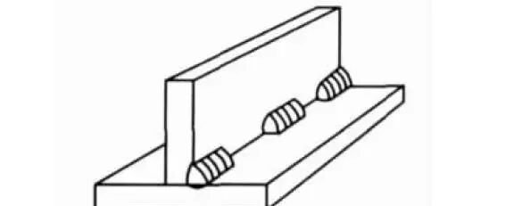
2 Intermittent welds
Another way to reduce the amount of weld filler is to make greater use of intermittent welding. For example, when welding reinforcement plates, the use of intermittent welding can reduce the amount of weld filler by 75 per cent whilst still ensuring the required strength.

3. Reducing the number of weld passes
Compared with using fine welding wire and applying multiple weld passes, using thick welding wire and applying fewer weld passes results in less distortion. When multiple weld passes are applied, the contraction caused by each pass accumulates, thereby increasing the total contraction of the weld. As can be seen from the figure, the welding process using fewer passes and a thicker electrode yields better results than the process using multiple passes and a thinner electrode.

It should be noted that the choice between using thick welding wire with fewer passes, or thin welding wire with multiple passes, depends on the material. Generally speaking, materials such as low-carbon steel and 16Mn are suitable for welding with thick wire and fewer passes, whilst stainless steel, high-carbon steel and similar materials are best suited to fine welding wire with multiple passes.
4 Anti-deformation technology
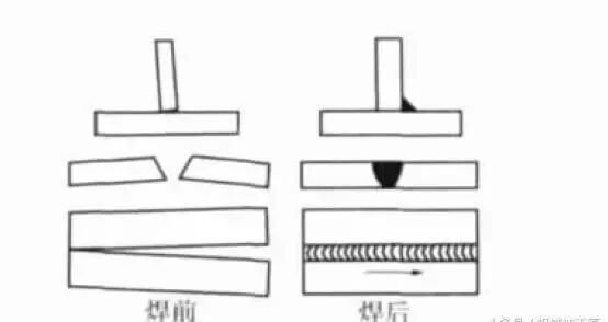
Prior to welding, components should be pre-bent in the direction opposite to that of welding distortion, or positioned at an angle, except in the case of overhead or vertical welding. The amount of pre-distortion required must be determined by trial. Pre-bending, pre-setting or pre-arching welding components is a simple method of utilising reverse mechanical forces to counteract welding stresses. When a workpiece is pre-set, deformation occurs that opposes the contraction stresses in the workpiece and the weld. The pre-welding deformation cancels out the post-welding deformation, thereby ensuring that the welded workpiece lies in an ideal plane.
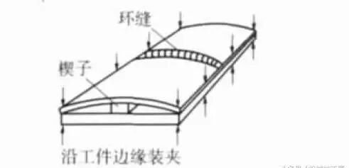
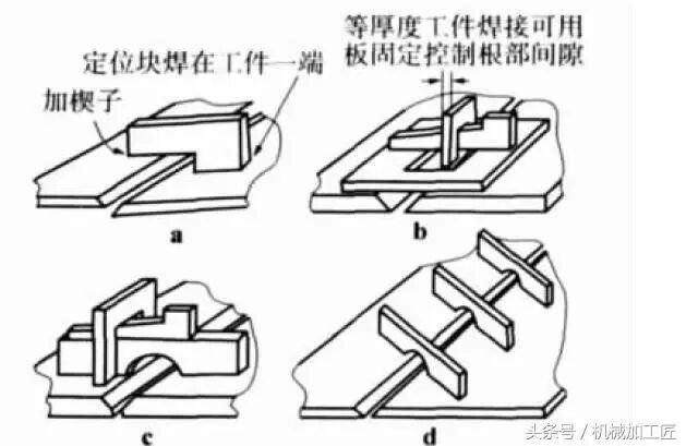
Another method frequently used to counteract contraction forces is to position identical welded workpieces in opposition to one another and clamp them securely in place. Pre-bending can also be carried out using this method; before clamping, wedges must be positioned at the appropriate points on the workpieces.
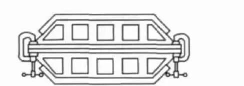
In the case of specialised, heavy-duty welded components, the required balancing forces may be generated either by the rigidity of the components themselves or by their relative positions. Should such balancing forces not be present, alternative methods must be employed to counteract the contraction forces of the welding material. The aim of this is to ensure that these forces cancel each other out. Counterbalancing forces may take the form of other contraction forces, mechanical constraints created by jigs and fixtures, constraints arising from the sequence in which components are assembled and welded, or even constraints resulting from gravity.
5 Welding sequence
Determine a reasonable assembly sequence based on the workpiece’s structural configuration, so that the workpiece contracts in the same position; create double-sided grooves at the workpiece’s neutral axis; employ multi-pass welding; and establish the sequence for double-sided welding, using intermittent welding for fillet welds; the shrinkage generated during the first pass is balanced by the shrinkage during the second pass; the jig and fixtures are capable of securing the workpiece in the required position, thereby increasing rigidity and minimising welding distortion, This method is widely used for welding small workpieces or small assemblies; however, as it increases welding stresses, it is only suitable for low-carbon steel structures with good ductility.
6 Removing shrinkage forces after welding
When cooling a weld, tapping is one method of counteracting its contraction forces; tapping causes the weld to elongate, allowing it to become thinner and thereby relieving stress (i.e. elastic deformation). However, when applying this method, care must be taken not to tap the root of the weld, as this may cause cracks to form. Generally speaking, the cover pass should not be tapped either.
As there is a possibility of weld cracks in the cover pass that could affect weld inspection, this may result in a hardening effect. Consequently, the application of this technique is subject to limitations; indeed, there are practical requirements to tap the welds within the multi-pass weld area (excluding the root pass and cover pass) in order to address issues of distortion or cracking. Heat treatment is another method of eliminating shrinkage forces, involving the control of the workpiece’s high-temperature conditions and cooling; in some cases, the workpiece is clamped and welded back-to-back, utilising such straightening conditions to achieve stress relief and minimise residual stresses in the workpiece.
6. Reducing welding time
During welding operations, heating and cooling occur, and the process of heat transfer also takes time. Therefore, the factor of time also influences deformation. Generally speaking, the aim is to complete the welding work as quickly as possible before larger workpieces undergo thermal expansion. Welding processes—such as the type and size of the welding rod, the welding current and the welding speed—all influence the extent of contraction and deformation in the workpiece. The introduction of mechanised welding equipment has reduced both the time required for welding and the amount of deformation caused by heat.
II. Other Methods for Reducing Welding Distortion
1 Water-cooling block
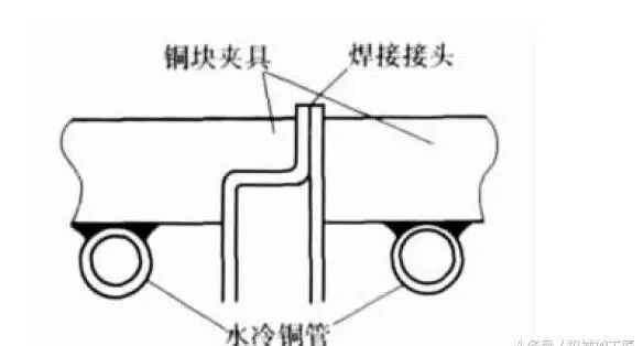
There are numerous techniques that can be used to control welding distortion in specific workpieces; for example, during the welding of thin sheets, water-cooled blocks can be used to dissipate the heat generated by the workpiece; copper tubes can be brazed or soldered to copper fixtures, and circulating cooling via water pipes can be employed to minimise welding distortion.
2 Wedge-shaped positioning plate
One technique used to effectively control welding distortion during butt welding of steel plates is the “positioning plate”, as shown in the figure. One end of the positioning plate is welded to a section of the workpiece, whilst the other end is wedged into a clamping plate; it is even possible to arrange multiple positioning plates in a row to maintain the positioning and fixation of the steel plates during welding.
3. Eliminating thermal stress
Except in special circumstances, the use of heat treatment to relieve stress is not the correct approach; measures to prevent or minimise welding distortion should be taken before the workpiece is welded.
III. Conclusion
In order to minimise the effects of welding distortion and residual stresses, the following points should be borne in mind when designing and assembling workpieces:
(1) Do not over-weld;
(2) Ensure the workpiece is correctly positioned;
(3) Intermittent welding should be used wherever possible, provided that the design requirements are met;
(4) Use the smallest possible solder pad dimensions;
(5) When carrying out beveled welds, the amount of weld metal in the joint should be kept to a minimum; consideration should also be given to joints where a double-sided bevel is used in place of a single-sided bevel.
(6) Endeavour to replace single-pass, alternating double-sided welding with multi-pass, multi-weld-pass welding wherever possible; carry out double-sided groove welding at the centreline of the workpiece; and, when using the multi-pass welding method, determine the sequence for double-sided welding.
(7) Use multi-pass, low-pass welding;
(8) A low-heat-input welding process is employed, which results in a higher deposition rate and a faster welding speed.
(9) Use a positioner to place the workpiece in the boat-shaped welding position; this position allows for the use of large-diameter welding wire and welding processes with a high deposition rate.
(10) Where possible, position the weld seam on the workpiece’s central axis and weld symmetrically;
(11) As far as possible, ensure that the heat from welding is distributed evenly by means of the welding sequence and positioning.
(12) Weld in the unconstrained direction of the workpiece;
(13) Use clamps, jigs and positioning plates for adjustment and positioning.
(14) Pre-bend the workpiece or pre-set the weld joint in the direction opposite to that of contraction.
(15) These components should be welded together in sequence, followed by the final assembly; this ensures that the welds remain balanced when the assembly is rotated about its central axis.
 Chinese
  Japanese
  English
  German
  Finnish
Leave a Reply
You must be logged in to post a comment.