
The present invention is defined withinResidual stressMachining deformationIn the field of control technology, this relates specifically to a method for controlling deformation during the machining of workpieces.
Background technology:
Machining deformation is caused by four factors: the initial residual stresses in the blank, clamping forces, cutting forces, and cutting heat, as well as residual stresses induced by the machining process; of these, the initial residual stresses in the blank have the greatest influence on machining deformation. Prior to machining a component, thermal stress relief and vibratory stress relief are primarily employed to homogenise the residual stress field and reduce its peak values, thereby controlling machining deformation; However, thermal stress relief is relatively energy-intensive and, like vibratory stress relief, suffers from the drawbacks of being difficult to control, producing less than ideal stress-relief results, and resulting in workpieces that still exhibit significant deformation.
Technology Enabling Elements:
To address the aforementioned issues, the present invention provides a method for controlling deformation during workpiece machining, which involves carrying out an initial machining operation to incorporate reserved reinforcing ribs, followed by leaving the workpiece to stand until its dimensions stabilise, followed by the removal of the pre-formed reinforcing ribs and a second machining operation. This approach effectively enhances the product’s bending strength, thereby reducing the extent of machining deformation in the workpiece.
A method for controlling workpiece deformation during machiningControl methods, comprising the following steps:
By using either a semi-analytical model based on processing deformation predictions or a finite element model, the deformation-sensitive directions and the locations of maximum deformation for the workpiece under test can be determined.
s2: Place ribs on the model of the workpiece under test; in doing so, the placement of these ribs must satisfy the following conditions:
The direction of the stiffener is parallel to the said deformation-sensitive direction;
the relative distance between the location of the stiffener and the location of the maximum deformation is less than a specified value;
The total thickness of the stiffener shall be compared with the dimension of the workpiece model in the direction of the stiffener thickness; it shall be less than 10 per cent of that dimension.
Based on a model of the workpiece under test featuring reinforcing ribs, an initial machining operation is carried out on the blank, thereby producing an intermediate workpiece with reinforcing ribs.
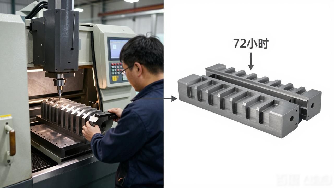
Leave the ribbed intermediate workpiece undisturbed for more than 72 hours so that, within the specified time period, its dimensional deformation remains below the set value, thereby ensuring a stable intermediate workpiece.
Step 5: Remove the reinforcing ribs from the stable intermediate workpiece to obtain the final machined workpiece.
Benefits:

The present invention provides a method for controlling machining deformation of workpieces. During the initial machining stage, reinforcing ribs meeting specific conditions are incorporated to enhance the workpiece’s bending stiffness, thereby significantly reducing machining deformation during this stage; The intermediate workpiece, which has been provided with reinforcing ribs during the initial machining stage, is left to stand for a period of at least 72 hours until stress redistribution is fully complete and its dimensions have stabilised, thereby obtaining a stable intermediate workpiece. Finally, the reinforcing ribs retained in the stable intermediate workpiece are removed by means of a secondary machining operation; At this stage, as the stresses have already been fully released and the amount of material removed during the removal of the reinforcing ribs is relatively small compared to the material removed during the first machining operation, no significant stress redistribution—such as that caused by the initial machining—will occur. Consequently, after the reinforcing ribs have been removed, the final machined workpiece will not undergo significant deformation again; It can thus be seen that the present invention, by employing a method of secondary machining utilising reserved reinforcing ribs, can effectively improve the workpiece’s bending stiffness, thereby reducing the final machining deformation. This approach can be used to guide the structural design of thin-walled, low-stiffness parts, and also provides a useful reference for determining the amount of allowance to be reserved during rough machining.
illustrate
Figure 1 is a flowchart illustrating a method for controlling deformation during workpiece machining provided by the present invention;
Figure 2 is a schematic diagram illustrating the process of machining the blank provided by the present invention;
Figure 3 shows a schematic diagram of the final structure of the machined workpiece provided by the present invention;
Figure 4 shows a schematic diagram of the structure of the blank provided by the present invention after a single machining operation.
practical way of doing sth.
To enable those skilled in the art to better understand the present invention, the technical solutions set out in the embodiments of the present application will now be described clearly and completely with reference to the accompanying drawings.
Refer to Figure 1, which illustrates a flowchart of a method for controlling workpiece deformation during machining as described in this embodiment. A method for controlling workpiece deformation during machining comprises the following steps.
By analysing the deformation patterns resulting from machining, and utilising semi-analytical predictive models or finite element models, it is possible to determine the sensitive directions within the workpiece under deformation, as well as the locations where maximum deformation is likely to occur.
s2: Ribs are to be added to the model of the workpiece under test, whereby the placement of said ribs must satisfy the following conditions:
The direction of the stiffener is parallel to the said deformation-sensitive direction;
the relative distance between the location of the stiffener and the location of the maximum deformation is less than a specified value;
The overall thickness of the rib shall be less than 10 per cent of the dimensions of the workpiece model to be tested in the direction of the rib thickness.
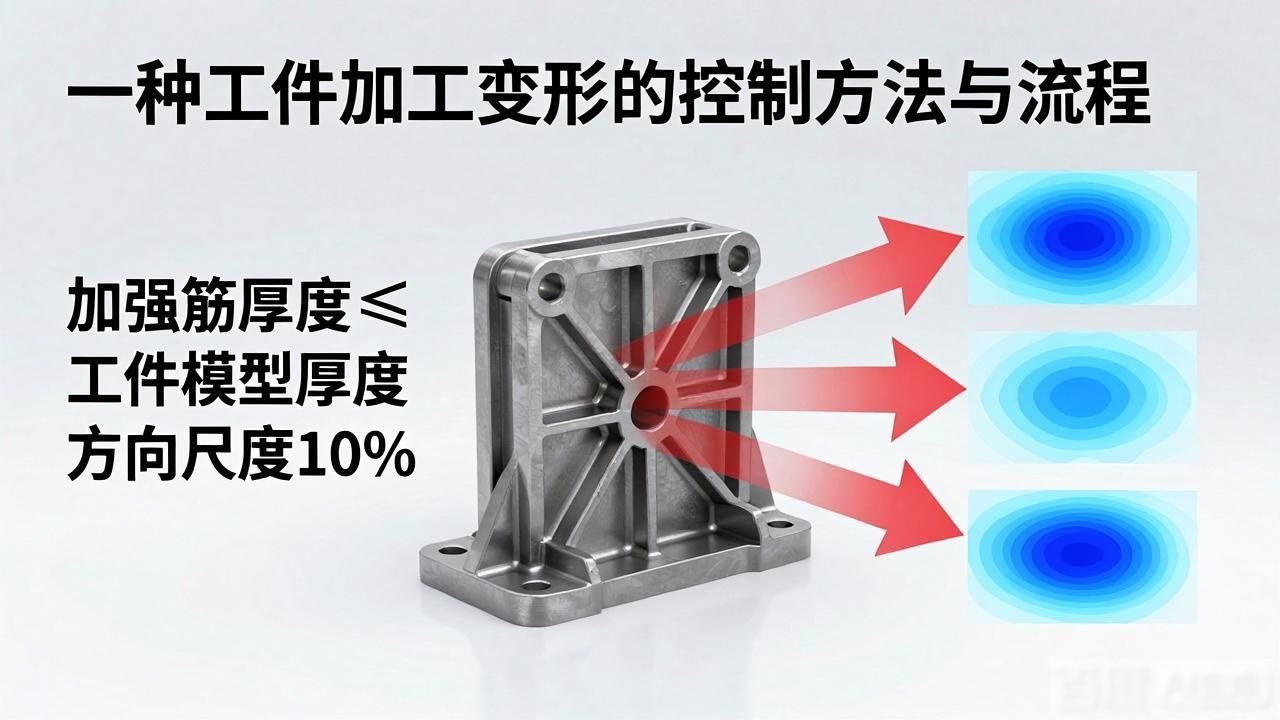
It is worth noting that, given the amount of material removed during secondary machining, this will affect the extent of deformation caused by stress redistribution. Theoretical simulation calculations show that when the overall thickness of the stiffener does not exceed 10 per cent of the workpiece model’s dimension in the direction of the stiffener’s thickness, the deformation resulting from the secondary machining is relatively minor.
s3: Perform the initial machining of the blank based on the model of the workpiece to be tested, which includes reinforcing ribs, thereby producing an intermediate workpiece with reinforcing ribs.
s4: Place the ribbed intermediate component in position and leave it undisturbed for more than 72 hours, so that, within the specified time period, the dimensional deformation of this ribbed intermediate component remains below the set value, ultimately resulting in a stable intermediate component.
s5: The stiffeners are cut out of the stabilised intermediate workpiece to produce the final machined workpiece.
Machining tests were carried out on the following five blank parts, with the aim of demonstrating that the method for controlling workpiece deformation provided in this embodiment can effectively reduce workpiece deformation during machining.
Refer to Figure 2, which illustrates the machining process of the blank provided in this embodiment; wherein Test Piece 1 is formed in a single machining operation rather than through secondary machining, whilst Test Pieces 2 to 5 are formed using the secondary machining process described in this embodiment; furthermore, Test Pieces 2 to 5 differ in terms of machining, specifically manifested in the placement of the reinforcing ribs and the overall thickness, which are not identical; they are not without difference, but rather differ from one another; they are not the same, and there are distinctions between them; they are not entirely consistent.
Please refer to Figure 3, which is a schematic diagram illustrating the structure used in this embodiment to machine the workpiece to its final state. As can be seen from Figure 3, this embodiment involves machining a blank made of 7075-T6 aluminium alloy into a workpiece in the form of a nine-square grid frame, hereinafter referred to as the ‘nine-square grid workpiece’. Referring to Figure 4, this figure is a schematic diagram illustrating the structure of the blank after a single machining operation in this embodiment; in this case, the workpiece has a width of 150 mm and a length of 300 mm. Given that the amount of material removed during the second machining operation will affect the magnitude of deformation caused by stress redistribution, theoretical simulations have revealed that the total thickness of the reinforcing ribs should not exceed 10 per cent of the workpiece’s width; as the deformation caused by the second machining is relatively minor. Consequently, in this embodiment, the total thickness of the stiffeners on the nine-grid workpiece at positions t1 and t2 is set to be less than 15 mm, whilst the total thickness of the stiffeners at positions t3 and t4 is set to be less than 30 mm. In this context, t1 represents the width of the outer edge of the nine-square-grid workpiece in the longitudinal direction; t2 refers to the width of the centre edge of the nine-square-grid workpiece in the longitudinal direction; t3 denotes the width of the outer edge of the nine-square-grid workpiece in the transverse direction; and t4 denotes the width of the centre edge of the nine-square-grid workpiece in the transverse direction. To be more specific, the dimensional characteristics of the fully machined test specimen 1, as compared with test specimens 2 to 5, which have undergone only a single machining process, are presented in Table 1:
Table 1
For the sake of clarity, the lengthwise direction of the nine-square-grid workpiece is defined as the x-direction, and its widthwise direction as the y-direction. As shown in Table 1, the dimensions of all edges of the final machined nine-square-grid workpiece are 2 mm. Compared with Test Piece 1, the width of the outer edge in the x-direction of Test Piece 2 has increased to 4 mm, whilst that of Test Piece 3 has increased to 8 mm; for Specimen 4, the width of the outer edge in the x-direction has increased to 8 mm, whilst the width of the outer edge in the y-direction has increased to 4 mm; for Specimen 5, the thickness of the central edge in the x-direction has increased to 8 mm.
Calculations using a semi-analytical model and finite element simulation show that, within 72 hours of the completion of the first machining operation, the warpage deformation of the bottom surface of Test Piece 1 undergoes only slight changes over time; It can thus be understood that, following the completion of machining, due to the combined effect of the residual stresses introduced during machining and the initial residual stresses, a certain amount of residual stress will still remain within the part. Consequently, after a period of time, the internal residual stresses will redistribute, thereby causing further deformation. After Specimens 2 to 5 had been left to stand for 72 hours, the second machining operation was carried out to remove the reserved reinforcing ribs. Specifically, for Specimen 2, a 2 mm rib was removed from the outermost edge in the x-direction; for Specimen 3, a 6 mm rib was removed from the outermost edge in the x-direction; and for Specimen 4, a 6 mm rib was also removed from the outermost edge in the x-direction; at the same time, 2 mm of the stiffener was also removed from the outermost edge of Specimen 4 in the y-direction; whilst for Specimen 5, 6 mm of the stiffener was removed from the edge at the centre of the x-direction.
In this embodiment, the dimensions of the nine-square-grid workpiece were measured periodically and on multiple occasions over the 720 hours following the completion of the final machining process. This enabled the identification of the pattern of deformation of the nine-square-grid workpiece over time, and it was determined that the dimensional changes of the workpiece tended to stabilise after a 72-hour rest period. Specifically, compared with the situation prior to the removal of the reinforcing ribs, although the deformation of the base surfaces of test specimens 2 to 5 all increased to some extent following the removal of the reinforcing ribs, when compared with test specimen 1—which was formed in a single machining operation—the maximum deformation of test specimens 2 to 5 was reduced by 5.43 per cent, 22.80 per cent, 23.32 per cent and 13.57 per cent, respectively. It can thus be concluded that, when retaining the outer-edge stiffeners, thinner reserved stiffeners result in greater final deformation than thicker ones; at the same time, when the thickness of the reserved ribs is the same, retaining the internal ribs results in less deformation than reserving thicker ribs; In other words, retaining the ribs within the workpiece—provided they are of greater thickness and the total thickness is less than ten per cent of the workpiece’s width—yields a more effective reduction in machining deformation; However, generally speaking, the workpiece with ribs left in place during the rough machining stage should be left to stand for seventy-two hours, until the stress redistribution in the semi-finished workpiece—which has undergone only a single cutting operation—is sufficiently complete and its dimensions are relatively stable, before the reserved ribs are removed. As the stresses in the semi-finished workpiece have already been sufficiently released, the removal of the reserved ribs—which is relatively minor—will not trigger significant stress redistribution, and the workpiece will therefore not undergo significant deformation; Consequently, by employing the method of reserving reinforcing ribs for secondary machining, this embodiment effectively enhances the workpiece’s bending stiffness, thereby minimising final machining deformation.
Of course, the present invention may have a variety of other embodiments; without departing from the spirit and scope of the invention, a person skilled in the art will certainly be able to make various corresponding modifications and variations based on the present invention, but such modifications and variations should all fall within the scope of the claims appended to the present invention.
 Chinese
  Japanese
  English
  German
  Finnish
Leave a Reply
You must be logged in to post a comment.