
The call for entries is now open – click here to view the event details
General Principles of Welding
2. During assembly, Hull StructureComponents or sections must maintain accurate dimensions, and assembly clearances must be uniform and consistent. Welding operations must not be carried out on any components or sections that do not comply with the requirements of the drawings, relevant standards or process specifications.
3. When carrying out welding operations on a ship’s hull structure, the work should generally be carried out in the order from the centre outwards to the left and right, and from the centre to the front and rear. For symmetrical structures, an even number of welders should carry out the symmetrical welding work simultaneously.
4. When carrying out welding operations on a weld, depending on the weld’s position within the ship’s structure, welding should be carried out either from the end closest to the centre of the structure towards the edge, or from the midpoint of the weld towards both ends.
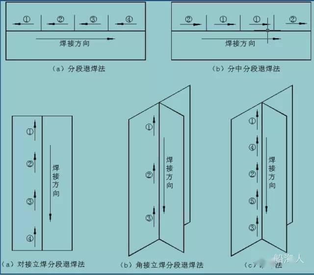
5. When performing manual arc welding (SMAW) or CO₂ welding on longer welds—where the length exceeds 1 m for SMAW and 2 m for CO₂ welding—the segmented back-welding method, the centred segmented back-welding method or the skip-welding method should be employed, as illustrated in Figure 1. For vertical-down welding, the through-weld method is used.

Figure 1: The back-welding method and the skip-welding methodWelding sequence
1. When welding multiple layers, the welding direction of each pass must be consistent; however, the welding directions of the different layers may be opposite. The joints of the weld passes should be staggered, with a minimum offset of 30 mm.
Welding sequence for each stage of hull construction
1. Panel assembly
When carrying out panel welding on a panel array, depending on the arrangement of the panel joints, the operation can be carried out in accordance with (a), (b), (c) and (d) in Figure 2.
Figure 2: Welding sequence for column plate assemblies
2. Hull components
The sequence of welding, inside the hull, for trusses and ribs, as well as frames and plates, must comply with the following requirements.
a) Where a structure contains both butt and fillet welds, the butt welds should be welded first, followed by the fillet welds; the specific sequence is shown in Figure 3(a) and (b).
b) Where a structure contains both vertical fillet welds and horizontal fillet welds, the vertical fillet welds must be welded first, followed by the horizontal fillet welds; the specific sequence is shown in Figure 3(c).
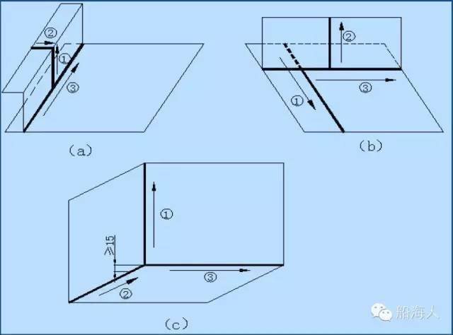
Figure 3: Welding sequence for internal components
3. Plan components (sections)
3.1 Where components require butt welding, this should be carried out in advance.
3. The welding sequence for the fillet welds between the plate and the various components is illustrated in Figures 4(a) and (b); Figure 4(a) is suitable for symmetrical structures.
3.3. If the end of a fillet weld is located at the joint between two sections, a length of approximately 200 mm should be left unwelded at that section; welding should be carried out only when the sections are joined, as shown in Figure 4(c).
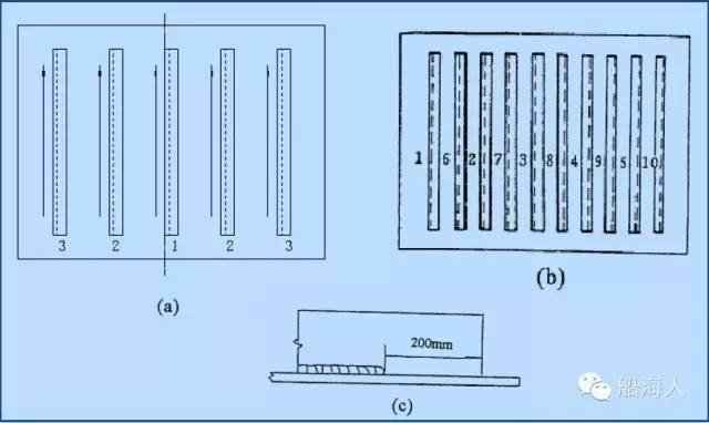
Figure 4: Welding sequence for fillet welds
4. Three-dimensional segmented production
4.1 Typical Sequence
a) In accordance with Clause 3, during the fabrication of flat sections, the fillet welds between the deck, the outer bottom plate and the stringers shall be completed in advance.
b) Once the tack welding of the longitudinal girders, web plates and inner bottom plate flat assemblies has been completed, following the sequence shown in Figure 5(a), an even number of welders shall weld the vertical fillet welds between the longitudinal girders, longitudinal stiffeners and web plates in a symmetrical manner within the 1 (1) – 2(2) – 3(3) – 4(4)…, the vertical fillet welds between the longitudinal girders, longitudinal ribs and rib plates.
c) Once the vertical fillet welds mentioned above have been completed, symmetrical welding shall be carried out by an even-numbered welder in the sequence and direction shown in Figure 5(b), welding the flat fillet welds between the longitudinal girders, web plates and bottom plates within the areas 1 (1) – 2(2) – 3(3) – 4(4)… in the areas where the longitudinal girders, web plates and bottom plates meet. However, a 200 mm section at the ends of the fillet welds located at the section closure edges must be left unwelded for the time being; welding of these sections will be carried out once the slipway is closed, as shown in Figure 4(c).
d) For the outer bottom plate assembly, after spot welding it to the stem plate, proceed to weld the symmetrical welds between the outer plate and the stem plate.
e) First, carry out the section-by-section turning; once the above-mentioned joining operations have been completed, proceed to weld the flat fillet welds between the longitudinal stringers, the rib plates and the outer plates, following the same sequence as in (c).
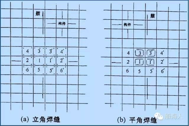
Figure 5: Welding sequence for segmented fillet welds
4.2 Penetration points
As shown in Figure 6(a), weld in the following order:
① Butt welds between welding patches;
② Fillet welds between the reinforcement and the patch plate;
③ Weld the fillet joints between the patch plate, the stiffener plate and the base plate.
For items ② and ③, the visible side shown in the diagram should be welded first.
As shown in Figure 6(b), start by soldering the visible side shown in the diagram; solder both sides in the following order:
① Fillet welds between the reinforcement bars and the web plates;
② Fillet welds between the reinforcement and the patch plate;
③ Weld the fillet weld between the patch plate and the rib plate.
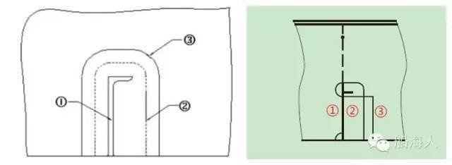
Figure 6: Welding sequence for through-bolts
5. Final assembly of the slipway
5.1 General Welding Sequence
When the ship is in the final assembly stage on the slipway, the standard welding sequence for the various sections is as follows: starting from the reference section, work proceeds sequentially in both the bow and stern directions. In the example shown in Figure 7, numbers 1, 2, 3, …, 12 represent the standard assembly sequence, and this sequence must not be deviated from.
Once the sectioned slipway has been hoisted into place, welding should be carried out as soon as possible; it is not permissible to hoist it into place without subsequently welding it.
Figure 7: Hull assembly welding sequence
5.2 Longitudinal closure joints
Following the sequence from a to b shown in Figure 8, the various sections—including the bottom section, the transverse bulkhead section, the side section and the deck—are assembled, after which they are welded together to form a circular assembly.
5.3 Transverse contraction joints
The sequence shown in Figure 8—from ① to ②, then to ③ and finally to ④—should be followed to carry out the butt welding operations between adjacent sections. However, welding of each transverse butt joint should only be carried out after the corresponding longitudinal butt joint has been completed.
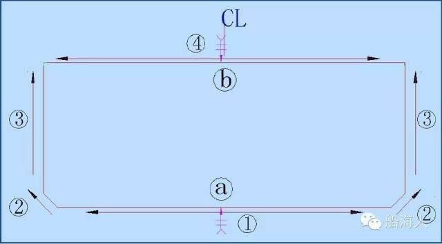
Figure 8: Typical closing weld sequence
5.4 Joints between structural members
As shown in Figure 9, the welding sequence is as follows:
① Butt jointing of panels;
② Joining of components;
③ Fillet welds between members and slabs.
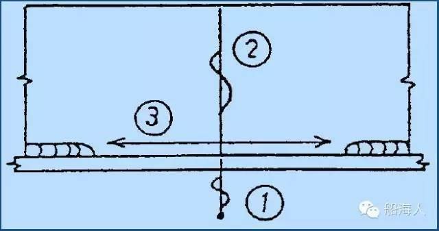
Figure 9: Welding sequence for the joint seam
6. Process holes
The welding sequence relating to the various process holes is shown in Figure 10. The number ‘3’ originally labelled on the left-hand side of the first image in the figure has been changed to ‘1’ following modification via this platform.
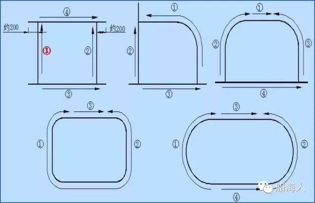
Figure 10: Welding sequence for process holes
 Chinese
  Japanese
  English
  German
  Finnish
Leave a Reply
You must be logged in to post a comment.