
1.1 Overview of sheet metal unfolding
Sheet-metal processing is usually carried out using the shaping properties of the metal itself, that is, for the kind of metal sheet with a certain thickness of its own, with the help of cutting, stamping and forming, bending and these process steps, so as to process and manufacture a single independent part, followed by the use of welding, riveting and other ways and means of assembly, and ultimately the completion of the component. The characteristic feature is that the thickness is always the same for the same part. In view of the sheet metal parts hold a lighter weight, higher strength, with conductive properties, lower cost, large-scale mass production performance is very good such and such a variety of characteristics, so the current sheet metal parts in the petrochemical industry, metallurgy, electronics and electrical appliances, communications, the automotive industry, medical equipment, and other areas of the scope of the use of a wide range of applications have been widely prevalent, for example, in the computer chassis, mobile phones, and so on. For example, in computer chassis, mobile phones and other products used in daily life, sheet metal has become an indispensable means of processing. As sheet metal is becoming more widely used, the design of sheet metal parts has become a critical part of the product development process. In this regard, it is important for mechanical engineers to have a good grasp of sheet metal design techniques. In this way, the sheet metal parts designed to meet the product function, appearance and other requirements at the same time, but also to meet the production and processing convenience, cost-effective and many other requirements.
In the sheet metal part design process, in addition to using engineering drawings to show the shape and dimensions of the parts, sheet metal unfolding drawings must also be used to show the shape and dimensions of the sheet material profile before production and processing of the sheet metal parts, so as to guide the sheet metal part production in order to place the material, arrange the samples, and produce them. This process of drawing a flat profile based on the three-dimensional shape of the part is sheet metal unfolding. By controlling the correct and effective method of unfolding sheet metal parts, we can not only ensure the accuracy of sheet metal parts, but also improve the processing efficiency and save costs.
1.1.1 Conventional sheet metal unfolding methods
Using the principles of descriptive and analytical geometry, which is the traditional method of unfolding sheet metal, a three-dimensional sheet metal part is flattened onto a plane to create the unfolded drawing. The surface shapes that make up sheet metal can be divided into two main categories, theoretical spreadable surfaces and non-spreadable surfaces. Spreadable surfaces are planar surfaces, cylindrical surfaces and conical surfaces, or surfaces divided by these surfaces. Non-expandable surfaces are spherical, toroidal, and other shaped surfaces. Expandable surfaces can be expanded accurately at a theoretical level, as the lengths of the corresponding vectors in the stereographic projection and unfolding diagrams are equal, and the surface areas of the parts before and after unfolding are also equal, whereas non-expandable surfaces are theoretically not able to be unfolded in a plane, and they can only be approximated as a number of expandable surfaces and then unfolded, and the traditional methods for unfolding sheet-metal sheets include template calculations, projection diagrams, and software assisted methods. The traditional methods of sheet metal unfolding include the template calculation method, the projection method, and the software method.
1. Projection diagramming
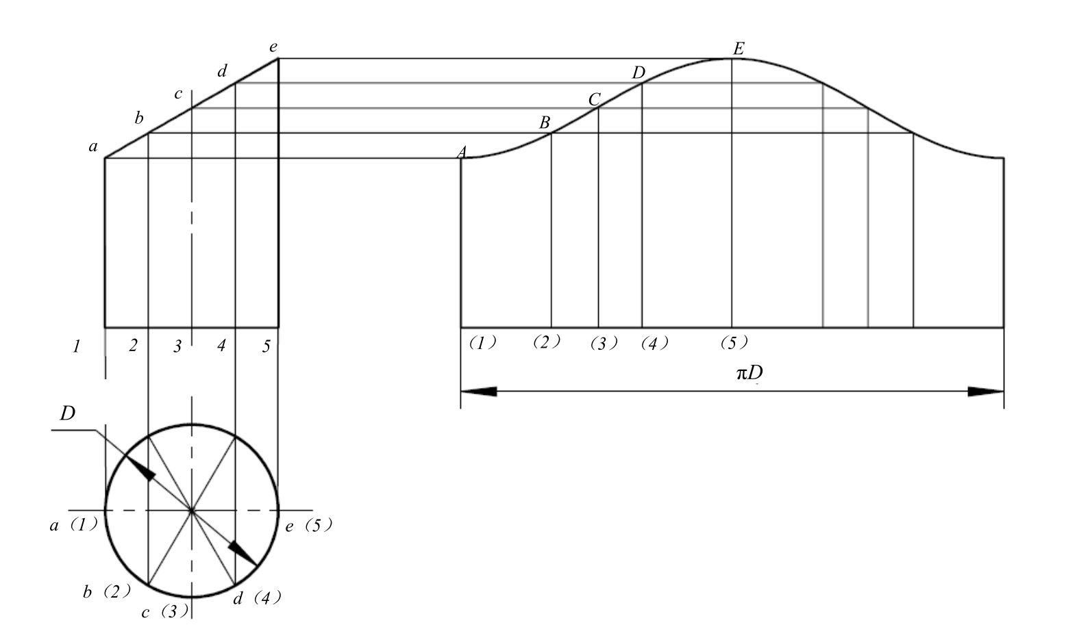
The projective method of unfolding sheet metal parts with the help of pictorial geometry and hand drawings, the specific methods available include the parallel, radial and trigonometric methods. The parallel method is used for the unfolding of cylindrical surfaces, the radial method for the unfolding of conical surfaces, and the trigonometric method for the approximate unfolding of non-developable surfaces.
This is done by dividing the surface of the cylinder into equal parts (points a to e) in order to subsequently determine the lengths of the polylines at the equal parts (a1 to e5), which is what the parallel line method of unfolding an obliquely-sectioned square cylindrical surface is used to do, and by unfolding the circumference of the base of the cylindrical surface into a straight line as part of the process, and by plotting the actual lengths of the polylines at the points of the straight line. This is also part of the process, as is drawing the actual lengths of the polylines at the equidistant points of the polylines, and then connecting the endpoints of the polylines (A to E) with curves, which completes Figure 1.1.1.

Figure 1.1.1 Unfolding an obliquely truncated square cylindrical surface by the parallel line method
2. Template calculation method
The template calculation method uses analytical geometry to calculate the unfolding of sheet metal parts, and its specific methods include real-length calculation method and coordinate calculation method, etc. The real-length calculation method uses analytical geometry to calculate the length of a line segment, i.e., a plain line, when unfolding, and then draws the unfolding drawing with the help of the length data, which is a more accurate data instead of the method of using the lines of the drawing as the length reference in the projection method, so that the result obtained is more accurate, but the outline of the unfolding drawing still has to be completed by drawing. However, the outline of the unfolded pattern still has to be completed by drawing, in other words, the outline of the final tracing still has a large error. The principle of the coordinate calculation method is similar to that of the real-length calculation method, in that when using the coordinate calculation method, the coordinates of the reference points in the unfolded outline are calculated directly with respect to a certain coordinate system, and the unfolded outline of the sheet metal is then plotted in that coordinate system.
3. Expansion of software-assisted methods
The software-assisted method of unfolding is based on the principle of template calculation method, with the help of software to automatically generate unfolding drawings, which are in DXF/DWG format and can be directly imported for editing and modification. However, the obtained drawings are generated in an ideal state, and the factors of plate thickness in the actual production are not taken into account, so it is not possible to obtain a complete three-dimensional model.
1.1.2 Use of sheet metal spreading for release
The traditional method of calculating sheet metal expansion is based on a theoretical ideal surface with zero thickness, however, in reality, sheet metal parts have a certain thickness. When the thickness of the sheet metal part is small and the accuracy requirement is not high, the thickness factor of the sheet metal can be ignored, but once the design of the sheet metal part requires a certain degree of accuracy, the plate thickness factor must be considered in the calculation of sheet metal unfolding. Therefore, the traditional method of sheet metal unfolding is only applicable to the manual production of material which does not require high accuracy.

In recent years, along with the popularity and application of CNC presses, laser, plasma, water jet cutting machines and CNC bending machines, the production efficiency of sheet metal parts has been greatly improved, and the processing efficiency of sheet metal parts is even more so. At the same time, newer requirements have been put forward to the design of sheet metal parts, and higher requirements have been put forward to the unfolding and placing of sheet metal parts, in which the use of three-dimensional CAD/CAM technology to carry out the design of sheet metal parts has It has become the mainstream. The idea of unfolding sheet metal parts with the help of 3D CAD software is to carry out the design and modelling of sheet metal parts or sheet metal assemblies in a 3D environment, and then automatically unfold the sheet metal parts in the software to generate three-view drawings and unfolding diagrams of the sheet metal parts, and the corresponding data can be directly imported into all kinds of advanced machining equipment to provide data references for the production and machining. The data can be imported directly into various advanced processing equipment to provide data reference for production and processing.
Among the popular 3D CAD software, there are CATIA, UG, Creo, Solid Edge and so on, which are all equipped with sheet metal part design module. Moreover, with its friendly interface, easy-to-learn and easy-to-use and easy-to-operate characteristics, the software has gained the affection of a wide range of sheet metal part designers. The use of it for sheet metal unfolding and release presents the following characteristics.
3D modelling is intuitive and easy to use, most sheet metal parts can be modelled with its help, and most sheet metal assemblies can be modelled with it, and the 3D model obtained in this way can be perfected for the electronic prototype of the whole product.
When modelling with the software, there is a wide variety of methods, including feature modelling, which can be used, design based on unfolded states, solid-surface transformation, and bending, which make it easy to create a wide range of sheet-metal models.
The 3D state of the sheet metal design process is intuitive, and when in this state, the structure of each part of the sheet metal part is clearly presented without any concealment, making it easy to modify, and it is possible to quickly export 2D drawings to implement automatic labelling.
Convenient unfolding, the system automatically unfolds the 3D model and can export the plane unfolding diagram.
The 3D model and drawing data are fully linked, so that when the dimensions of a sheet metal part are modified inside the 3D model, its three views are automatically updated, as well as the unfolding drawings.


No comments