
Technical Brief:
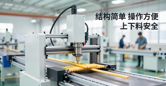
This patent proposes a mechanism with automatic loading and unloading function for the problem of low efficiency and great safety hazards when loading and unloading is carried out manually in the traditional bar processing. The mechanism with the help of hydraulic pressure to drive the lifting body, by its and pneumatic horizontal movement device to cooperate with each other, to achieve the block in a synchronous manner to lift and do lateral displacement effect, can automatically complete the bar to be processed into the processing position, as well as has been completed the processing of the bar for loading and unloading operations, so as to enhance the safety and efficiency of the operation process.
Keywords: automatic bar loading and unloading, hydropneumatic drive, automation machinery
Automatic loading and unloading mechanism for bars
[Patent Abstract] The present invention discloses a technical solution concerning an automatic loading and unloading mechanism for bars. On a bed, a guiding sleeve is fixed vertically. Inside the guiding sleeve, a riser bar is provided. As for the upright bar, a lifting body is fixedly connected to its upper end. A slider is fixed above the lifting body. A linear guide which is compatible with the slider is connected to a horizontal driving device. Above the linear guide, a first and a second carrier are fixed, which are used to support the bar. Between the lifting body and the bed, a lifting drive mechanism is provided. This automatic loading and unloading mechanism is simple in structure, easy to operate, more convenient in control, safe and reliable in loading and unloading, which saves time and labour, and also improves work efficiency.
Patent Description] Automatic loading and unloading mechanism for bar material
[Technical field]
The present invention relates to an automatic loading and unloading mechanism for bars, which is used in machining equipment, where the loading operation is carried out during the processing of the bars, during which the unloading operation is also carried out, is the case.
[Background technology]
Machining equipment, in order to carry out the processing of the bar at the time, the need to carry out the feeding operation, that is, to be placed in the bar on the processing position, and then the implementation of the cutting process, to be processed after the end of the operation, but also to carry out the operation of the material, that is, has been processed bar to be unloaded. At present, most of the feeding and discharging operations are completed manually, for the heavier bars, the use of lifting mechanism to operate its up and down, so that both time-consuming, but also consume manpower, but also hidden safety hazards.
[Contents of invention]

The present invention has such a purpose, that is to provide a mechanism, the mechanism has some characteristics, its structure is simple, it is good to operate, it is easy to control, it is safe loading and unloading, it saves time and effort, it is low intensity of work, this mechanism for the automatic loading and unloading of bar material mechanism, which can overcome the shortcomings of the existing technology.
The bed is vertically fixed with a guiding sleeve, the guiding sleeve is equipped with a vertical rod, the upper end of the vertical rod is fixedly connected to the lifting body, the lifting body is fixed with a slider, and the slider is connected to the linear guide with a horizontal drive device, the linear guide is fixed with a first block and a second block supporting the bar material, and there is a lifting and lowering drive mechanism between the lifting body and the bed.
There is a cylinder connected with a pneumatic device on top of the lifting body, which is the horizontal driving device mentioned, and the outer end of the piston rod matched with the cylinder is connected with the linear guide mentioned. The cylinder is installed vertically above the bed and the hydraulic control device is connected to each other, this cylinder is the lifting and lowering drive mechanism, and the cylinder is matched with the piston rod outside the end of the lifting and lifting body is connected to each other.
There are two linear guides as described, and the two are set in a parallel state. At one end of the linear guide, there is a connecting plate. The end of the piston rod, which is to be connected to the cylinder, is connected to the linear guide with the help of this connecting plate.
The invention has automatic loading and unloading mechanism for bar material, when the workpiece on the processing position is processed, the bar material on the position to be processed is in the waiting condition, the first bracket is in the position below the bar material to be processed, and the second bracket is in the position below the processing position, after the processing is completed, the oil cylinder generates the action and drives the lifting body to rise, at the same time, the air cylinder, the slider, the linear guideway, the first bracket and the second bracket rise together, at this time, the vertical rod moves upward relative to the guiding sleeve and plays the role of guiding. At the same time, the cylinder, slider, linear guide, first block and second block go upward, at this time, the vertical bar moves upward with respect to the guiding sleeve and plays the role of guiding. The processed bar is detached from the processing position and placed on the second pallet, at the same time, the bar to be processed is placed on the first pallet, and then, the action of the cylinder drives the linear guide to the right relative to the slider in the horizontal direction, so that the first pallet to be processed bar into the processing position, the second pallet to be processed bar into the lower material workstation to achieve the next material, and then the cylinder returns to the original position, and then the cylinder also returns to the original position. The cylinder then returns to its original position, followed by the air cylinder, arriving at the initial position to carry out the next cycle. This automatic loading and unloading mechanism is simple in structure, convenient in operation, easy in control, safe in loading and unloading, which saves time and effort and improves the working efficiency.
[Patent Attachment]
[Illustration]
Figure 1 is a schematic diagram of the structure of the present invention [specific embodiment];
FIG. 2 is a top view schematic diagram of that shown in FIG. 1.
[Specific implementation modalities]
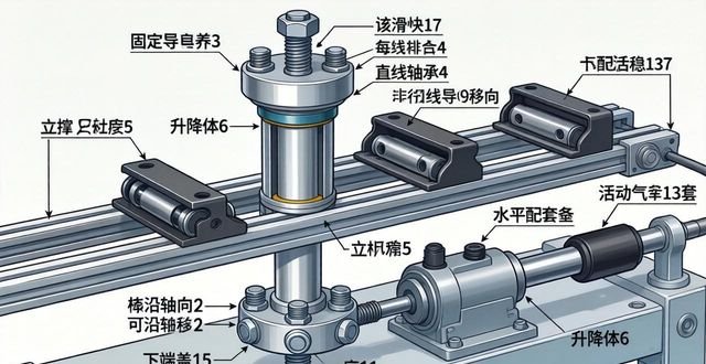
As shown in Figure 1, I is a bed of a machine tool, on which a guiding sleeve 3 is fixed vertically, in which a rod 5 is provided by means of linear bearings 4, and which is capable of axial movement. The lower part of the guiding sleeve 3 is fixed by means of fixing bolts 2, which are six in number and evenly distributed along the circumference. The lower part of the guide sleeve is connected to the lower cover 15 by means of screws, and the upper part of the guide sleeve 3 is bolted to the upper cover 12 of the guide sleeve. 6 is fixedly connected to the upper part of the riser 5, and the lower part of the riser 6 is bolted to the bottom cover 11, which is also shown in FIG. 2. Above the lifting body 6, two rows of sliders 17 are fixed, two in each row, with which two linear guide rails 9 are set up in parallel, the linear guide rails 9 are connected to a horizontal driving device, the horizontal driving device is installed on the lifting body 6 with a pneumatic device connected to the cylinder 13, and the piston rod 7 matched to the cylinder 13 is connected to the connecting plate 8 at its outer end, and each of the linear guide rails 9 is connected to the connecting plate 8, and the connecting plate 8 moves with the piston rod 7 as the connecting plate 8 moves with the connecting plate 8. When the connecting plate 8 moves with the piston rod 7, it can drive each linear guide 9 to move. Above the linear guide rails 9, parallel first and second brackets 10 and 14 are fixed for supporting the bar material. Between the lifting body 6 and the bed I, a lifting drive mechanism is provided. On the bed body I, a cylinder 16 is fixed vertically to the hydraulic control device, which is part of the lifting drive mechanism, and there is a piston rod mated with the cylinder 16, the outer end of which is connected to the lifting body 6.
The automatic loading and unloading mechanism of the bar of the present invention, when the workpiece in the processing position is processed, the bar to be processed is in a waiting situation, the first block 10 is in the lower position of the bar to be processed, and the second block 14 is in the lower position of the processing position, after the completion of the processing, the oil cylinder generates the action and drives the lifting body 6 upward, and at the same time, the cylinder 13, the slide 17, the linear guide 9, the first block 10 and the second block 14 rise upward together. At the same time, the cylinder 13, slide 17, linear guide 9, the first block 10, the second block 14 together rise up, at this time the vertical bar 5 relative to the guide sleeve 3 towards the upward movement and play a role in guiding. The processed bar material which has been detached from the processing position is appropriately placed on top of the second pallet 14, and at the same time, the bar material to be processed is placed on top of the first pallet 10, and then the linear guide 9 is driven to move towards the right in the horizontal direction with respect to the slide 17 by the action of the pneumatic cylinder 13, resulting in the first pallet 10 feeding the bar material to be processed into the processing position, and the second pallet 14 feeding the processed bar material to the lower material station for discharging. The second pallet 14 sends the processed bar to the unloading station for unloading, after which the cylinder 16 returns to its original position, followed by the cylinder 13, which also returns to its original position, arriving at the initial position to carry out the next cycle. This automatic loading and unloading mechanism has a simple structure, has the characteristics of good operation, easy to control, safe loading and unloading situation, can save time and effort, but also improve the work efficiency.
[Claims]
1. There is a mechanism for automatic loading and unloading of bars, which is characterised by the following features: in the body of the bed (I), the guiding sleeve (3) is fixed vertically, and the guiding sleeve (3) is equipped with a riser (5), the upper end of which is fixedly connected to a lifting body (6), a slider (17) is fixed on the upper side of the lifting body (6), and a linear guideway (9), which is matched with the slider (17), is connected to a horizontal driving device, a first support block (10) and a second support block (14), and a lifting drive mechanism is provided between the lifting body (6) and the body of the bed (I). The linear guide (9) matched with the slider (17) is connected to a horizontal drive device, and a first support block (10) and a second support block (14) are fixed above the linear guide to support the bar material, and a lifting and lowering drive mechanism is provided between the lifting body (6) and the bed (I).
2. The automatic loading and unloading mechanism for bars according to claim 1, having the following features: said horizontal driving device is installed on top of the lifting body (6) with a cylinder (13) connected with a pneumatic device, and the external end of the piston rod (7) matched with the cylinder (13) is connected with said linear guide (9); said lifting and unloading driving mechanism is fixed vertically on the bed (I) with an oil cylinder connected with a hydraulic control device, and the external end of the piston rod matched with the oil cylinder is connected with said linear guide (9); said lifting and unloading driving mechanism is fixed vertically on the bed (I) with an oil cylinder connected with a hydraulic control device, and the oil cylinder connected with an oil cylinder connected with an oil cylinder connected with an oil cylinder connected with the oil cylinder connected with the oil cylinder connected with a hydraulic control device. Said lifting drive mechanism is a cylinder vertically fixed on the bed (I) and connected to the hydraulic control device, and the external end of the piston rod (6) matching the cylinder is connected to the lifting body (6).
3. Automatic loading and unloading mechanism for bars according to claim 2, having the feature that two linear guides (9), which are set parallel to each other, are present at one end of the linear guides (9) with a connecting plate (8), and that the end of the piston rod (7), which matches with the pneumatic cylinder (13), is connected to the linear guides with the help of the connecting plate (8).
[Document number] B23Q7/
The date of disclosure is 5 March 2014, the date of filing is 6 November 2013, and the date of priority possession is also 6 November 2013.
Peng Xiaodang, Zhu Enlin, He Jun, Zhang Lei, Jin Minglai and Fang Chenbin are the inventors and Dalian Machine Tool (CNC) Co. is the applicant.


No comments