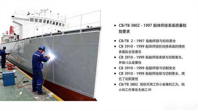



The following sets out the general procedure for replacing hull bulkhead panels. Firstly, scope of application: this procedure applies to steel bulkhead panels on seagoing vessels, and also to the replacement of dry compartment bulkheads beneath transverse bulkheads; Secondly, referenced documents: the provisions of the following documents become part of this general procedure by virtue of their reference herein; For any document bearing a specific date, all subsequent amendments (excluding errata) or revised editions shall not apply to this procedure; however, the parties entering into an agreement based on this procedure are encouraged to consider whether the latest versions of these documents may be adopted. Where a referenced document bears no specific date, the latest version shall apply to this general procedure. These include CB/T 3802 – 1997 ‘Requirements for Surface Quality Inspection of Ship Hull Welds’, CB 3910 – 1999 ‘Safety in Ship Welding and Cutting’, and the CB/T Chinese Shipbuilding Quality Standards, furthermore, there is CB/T 3584 – 94 Technical Requirements for the Repair of Ship’s Bulkheads, Side Walls and Deck Structures, and CB/T 3586 – 1994 Technical Requirements for Localised Patching and Large-Area Replacement of the Ship’s Hull, as well as CB/T 3587 – 1994 Technical Requirements for Ship Hull Structure Repairs, which refers to the selection of materials. In this context, ship hull structural steels are classified into two main categories: general-purpose ship hull structural steel and high-strength ship hull structural steel. Steels used for general ship structure are classified into grades A, B, D and E, whilst high-strength ship structure steels are classified into four grades: A, D, E and F. Specifically, these include A32, D32, E32 and F32, as well as A36, D36, E36 and F36, and furthermore A40, D40, E40 and F40, 3.2 Selection of steel plates: The selection of steel plates requires consultation of the original ship’s transverse bulkhead drawings, namely ‘W.T. IN CARGO HOLD’. As a general rule, the thickness of the replacement steel plate must not be less than that specified in the original drawings, nor must the material grade be lower than that specified in the original drawings; If no drawings are available for the vessel, the thickness of the plate should be measured on site, and samples taken for chemical composition and mechanical property tests; based on the results of these measurements and tests, the appropriate thickness and material grade for the replacement plate shall be determined; furthermore, these must be submitted to the surveyor and the shipowner for approval before use. 4. The scope of the replacement work must be determined on site by the shipowner, surveyor, chief engineer and vessel-specific works supervisor, and marked with paint. During construction, work must be carried out in strict accordance with the previously defined scope of works; under no circumstances may the scope of works be arbitrarily expanded or reduced. 5. With regard to safety requirement 5.1, a thorough understanding of the layout of the area where the plates are to be replaced and the surrounding compartments—such as the upper and lower dry bulkheads and the double bottom—must be obtained; work may only commence after a hot work permit has been issued. If an adjacent compartment is an oil tank where hot work is prohibited, a clearly visible warning line must be marked, with a distance of at least 200 mm from the oil tank. Regarding 5.2, safety harnesses must be securely fastened when working at height, in accordance with the principle of ‘high attachment, low use’. With regard to 5.3, when cutting, a length of at least 100 mm must be left uncut at each of the four corners of every steel plate; cutting may only commence once the hook is under load. However, where corrugated walls are severely corroded, the length of the section to be retained should be appropriately increased. 5. When using a winch to hoist steel plates, based on the current load capacity of the winch on site (3 tonnes), the weight of each cut section must under no circumstances exceed 2.5 tonnes, and it must be strictly ensured that the weight of each cut section does not exceed the specified safe working load of the wire ropes, pulleys and other rigging used to hoist it. When welding the winch to the inner bottom plate, care must be taken to verify that the inspection results for the inner side of the double bottom are satisfactory and that the conditions for hot work are met. The relevant operations may only be carried out after the inspection has confirmed compliance. The steel wire rope used with the winch must enter the winch in a straight line; it must not form a kink due to obstruction by scaffolding steel tubes. Otherwise, this may cause the scaffolding to be pulled down or bent. When using a single-handle pulley with the winch, the connecting hook must be attached using a shackle; under no circumstances should holes be drilled directly into the steel plate for this purpose. 5.7 The safety operating procedures established by the China State Shipbuilding Corporation and the enterprise must be strictly adhered to. 6. Marking out 6.1 Around the cutting line, any oil, rust or dirt must be thoroughly cleaned away; the area to be cleaned extends 30 mm to 50 mm on either side of the cutting line. 6.2 Prior to cutting, original components on the bulkhead, such as cross-bulkheads and ramp plates, must be marked to facilitate reinstallation. 6.3 The cut must remain parallel to the original plate joints in both the vertical and horizontal directions. 6. Replaced plates must have a minimum length of more than 300 mm and a minimum width of more than 300 mm; see Figure 1. 6.5: Parallel welds must be maintained at a certain distance; the parallel distance between butt welds must not be less than 100 mm, whilst the parallel distance between butt welds and fillet welds must not be less than 50 mm. In 6.6, where panel joints are located in areas of linear variation, sharp-angled intersections must be avoided; where intersections do occur, the angle of intersection α must be greater than 15°; otherwise, the panel joints must be adjusted to form a stepped or orthogonal configuration. 7. With regard to the cutting and blanking of old plates, Section 7.1 stipulates that when replacing corrugated-wall plates, vertical plate layout is permitted, i.e. the grain direction of the steel plate must align with the height direction; when replacing straight-wall plates, transverse plate layout is generally adopted, although in special circumstances, this must be approved by the surveyor. 7.2 describes the fabrication of corrugated walls: prior to cutting, a template must be produced to specify the angles of the corrugated walls, and the actual developed length must be calculated; fabrication must be carried out in accordance with the template, with the tolerance between the finished product and the template being ±1.5 mm. 7.3 It is mentioned that, where possible, new plates should be cut to size without allowing for excess material in order to improve efficiency; if assembly without excess material is not feasible, efforts should be made to re-cut old plates. 7.4 For bending, bend angle lines—that is, the bending lines—must be marked on the new plates. Furthermore, during the bending process, defects such as creases, peeling or sharp edges must not occur, and the finished product must be checked for conformity with the template. The machining tolerance must be less than or equal to 2 millimetres, and edge creases must also be less than or equal to 2 millimetres. 7.5 When replacing large areas of plate, submerged arc welding should be used as far as possible to join the plates on the jig, thereby improving efficiency. 7.6 If cutting along the original plate seam, the end of the original seam should extend for at least 150 millimetres; if cutting away from the original plate seam, the ends must be rounded with a radius (R) of at least 10t, where t is the plate thickness, and the radius must not be less than 100 millimetres; please refer to Figure 1. 7.7. During cutting, care must be taken not to damage any intact internal components; the depth of the cut must not exceed 0.5 mm. If this limit is exceeded, the area must be repaired by welding and then ground smooth. 7.8. When cutting vertical walls, the vertical cutting line must remain parallel to the vertical stiffeners; the gap formed by the cut must be at least 150 mm from the fillet weld of the stiffeners, and in exceptional circumstances must not be less than 75 mm. 7.9. Once the scope of plate replacement has been determined, the edges of the old plates shall, as far as possible, be cut to size using a semi-automatic cutting machine or an all-position cutting machine. 7.10. The cut at the joint between the new and old plates shall, as far as possible, be made using a semi-automatic cutting torch. The cut edges must be kept straight, with a tolerance of ±1.5 mm. 7.11, Large areas.



 Chinese
  Japanese
  English
  German
  Finnish
暂无评论内容