
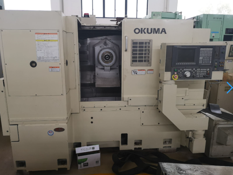
There is no clear international definition of a multi-tasking machine tool; the field is currently undergoing a process of innovation and development. Multi-tasking machining is also known as complete machining or multi-functional machining. In the early days, machining centres were referred to as composite machining centres. However, with the continuous development and advancement of composite machining technology, today’s composite machining centres differ fundamentally from those previously described as such. Composite machining centres perform multiple machining operations on a workpiece with a single set-up, which reduces machining time and also enhancesmachining accuracy, which is why it has proved popular with users. CNC turning-milling composite machine tools are a major type of composite machining centre; they typically perform face milling on a CNC lathe, drilling and tapping, and milling operations such as grooving. They combine turning, milling and boring functions, enabling the ‘single-set-up, complete-processing’ concept.

In turning-milling combination machine tools, there are four fundamental movements: the rotation of the milling cutter, the rotation of the workpiece, the axial feed of the milling cutter, and the radial feed. Depending on the relative position of the workpiece’s axis of rotation to that of the cutting tool, combined turning and milling operations can be broadly categorised into axial turning and milling, orthogonal turning and milling, and general turning and milling. Of these, axial turning and milling and orthogonal turning and milling are two widely used turning and milling methods. As the rotational axes of the milling cutter and the workpiece are parallel in axial turning and milling, this method can be used to machine not only external cylindrical surfaces but also internal bore surfaces. In orthogonal turning and milling, as the milling cutter is perpendicular to the workpiece’s axis of rotation, it is not possible to machine internal bores when their diameters are relatively small. However, when machining external cylindrical surfaces, as there are no restrictions on the longitudinal travel of the milling cutter and relatively large longitudinal feeds can be employed, the process is relatively efficient for this type of machining.
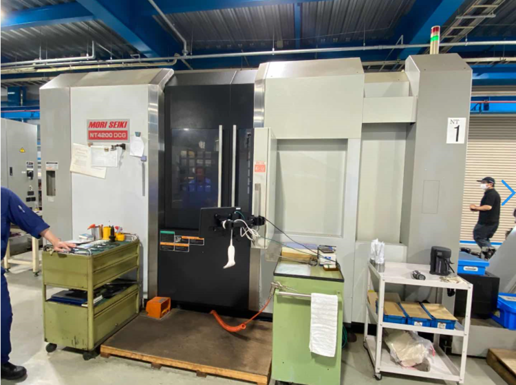
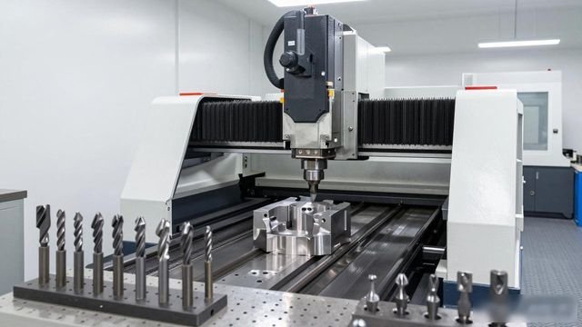
Compared with conventionalnumerical control machiningIn terms of manufacturing processes, combined turning and milling offers a number of advantages, which are specifically reflected in the following aspects: Firstly, it shortens the product manufacturing process chain, thereby improving production efficiency. Secondly, turning-milling composite machining allows for the installation of a variety of specialised cutting tools; by employing innovative tool arrangement methods, it reduces tool changeover time, thereby improvingprocessing efficiency. Furthermore, combined turning and milling enables all or most machining operations to be completed in a single set-up, which significantly shortens the product manufacturing process chain. On the one hand, this reduces the auxiliary production time caused by changes in clamping arrangements; on the other hand, it also reduces the lead time for the manufacture of tooling and fixtures as well as waiting times, thereby significantly improving production efficiency.
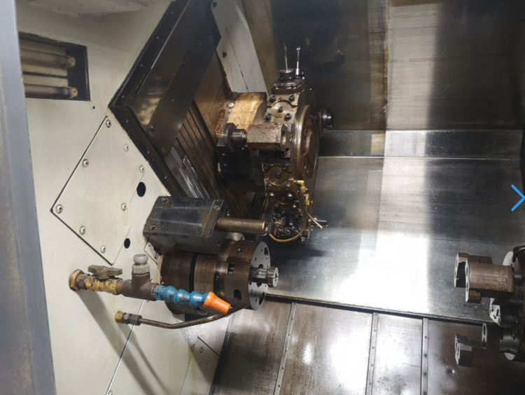
Reducing the number of set-ups improves machining accuracy. Fewer set-ups prevent the accumulation of errors caused by changes in the positioning reference. At the same time, most turning-milling combination machines are equipped with in-process inspection capabilities, enabling the on-the-spot monitoring of key manufacturing data and precision control, thereby enhancing the machining accuracy of the product; The machine bed is designed as a high-strength, monobloc unit, enhancing its capacity for heavy-duty machining of difficult-to-machine materials; the machine is equipped with an automatic feeding system, enabling automatic loading to maintain continuous operation and essentially achieving assembly line-style production with a single machine.
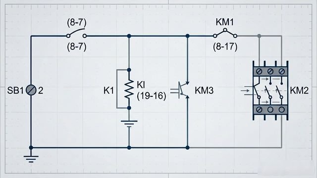
Press ‘Taiwan’Mill-Turn Machining CentreWhen SB1 is pressed, its normally open contacts (8–7) allow K1 and KM3 to be de-energised and released; contact Kl (19–16) opens, causing KM1 to be de-energised and released, thereby cutting off the power supply to the main motor. When SB1 is pressed on the CNC machine tool, its normally open contacts (8 – 17) close and energise the following circuit: the power supply line runs from (8) → SB1 (8 – 17) → K1 (17 – 21) → KMI (21 – 20) → the coil of KM2 → the power supply line”. On the Taida turning and milling centre, this causes the reverse-rotation contactor KM2 to receive power and thus operate. Once KM2 has operated, its moving contacts (8–17) allow the self-locking circuit to be energised; when pushbutton SA1 is released, KM2 remains energised and continues to operate.
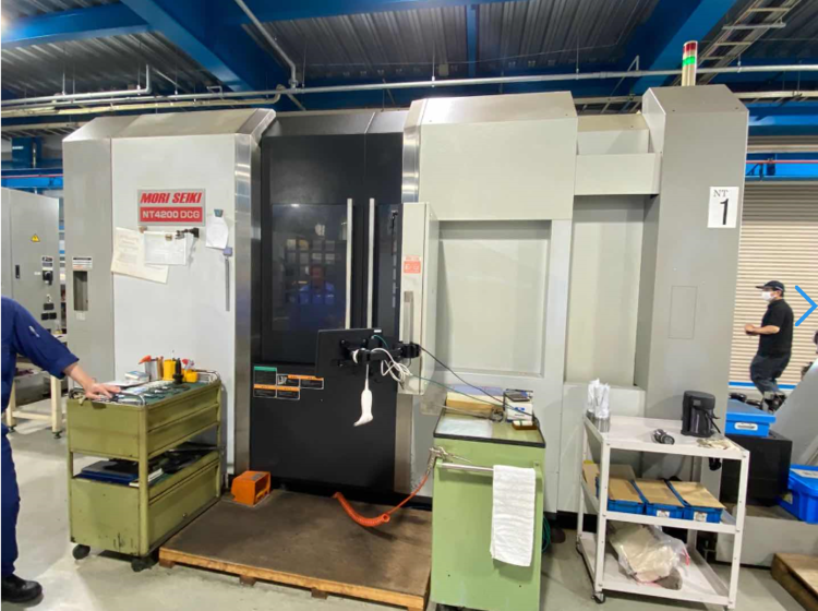
CNC lathes and mill-turn centres represent a machining method characterised by stability, speed and precision. The combination of a turret and a comb-type design reduces the idle travel distance of the tool changer and enhances machining efficiency. The comb-type tool holder enables simple milling operations to be carried out simultaneously on the lathe, thereby eliminating the hassle and inconvenience associated with secondary machining. Equipped with a precision spindle, which offers stability and high cutting efficiency. The 15° inclined bed design balances mechanical considerations with chip evacuation, addressing the challenge of chip removal that is often difficult to resolve fully with a turret and comb-type configuration; The linear guide design meets users’ requirements for cutting loads and rapid traverse, resulting in a fine turning finish on workpieces whilst maintaining consistent precision.
 Chinese
  Japanese
  English
  German
  Finnish
Leave a Reply
You must be logged in to post a comment.