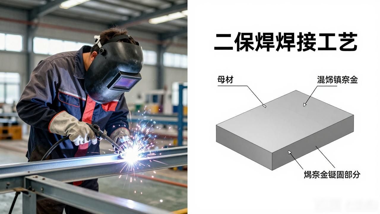



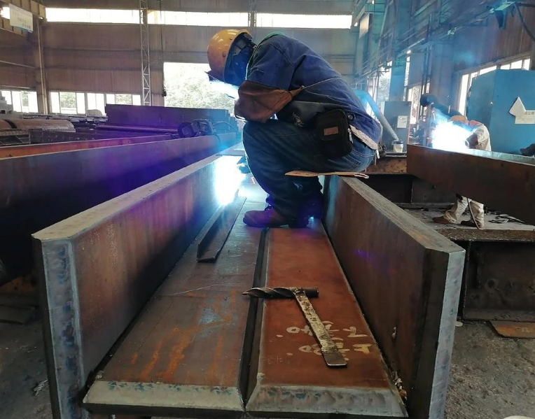
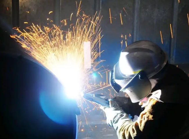
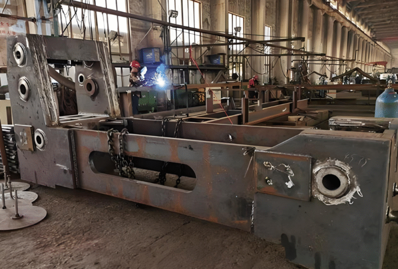
cemented carbide weldingWelding process, that is, the CO₂ gas shielded welding process, which is suitable forsteelworkThe CO₂ gas-shielded arc welding procedure specifications drawn up apply to all types of steel structures manufactured by this company. This standard sets out the basic requirements for CO₂ gas-shielded arc welding of carbon structural steel; it should be noted that where a product has a specific process standard, that standard shall take precedence. The reference standard used in its compilation is ‘Basic Formation and Dimensions of Weld Grooves for Oxy-fuel Welding, Manual Arc Welding and Gas Shielded Arc Welding’ (GB 985-88). With regard to terminology, ‘base metal’ refers to the material being welded, whilst ‘weld metal’ refers to the molten filler metal and those parts of the base metal formed after solidification. 2.3 Introduction to interpass temperature: During multi-pass welding, this refers to the minimum temperature that must be maintained between adjacent weld passes before proceeding to the next pass. 2.4 Explanation of ship-shaped welds: Welding carried out in the horizontal position on T-joints, cross joints and corner joints. 3. Preparation for welding: 3.1 Conduct a welding procedure qualification in accordance with the drawing requirements. 3.2 Preparation of materials: 3.2.1 The steel products and welding consumables must comply with the requirements specified in the design drawings. 3.2.2 Welding wire must be stored in a dry, well-ventilated area and kept under the supervision of a designated person. 3.2.3 Welding wire must be free from oil and rust prior to use. 3.3 The principles governing groove selection are to minimise distortion during the welding process, economise on welding consumables, improve labour productivity and, consequently, reduce costs. 3.4 Working Conditions, 3.4.1 states that should wind speeds exceed 2 m/s, welding operations must be suspended or appropriate wind-protection measures must be implemented. 3.4.2 specifies that the relative humidity in the work area must be less than 90 per cent; outdoor welding is prohibited in rainy or snowy weather. 4 Construction Process, 4.1 Process Flow: Clean the welding area; inspect components, assembly, machining and positioning; adjust welding parameters in accordance with the process documentation; carry out welding in a reasonable sequence; conduct self-inspection and mutual inspection; weld repair, grinding of welds to acceptable standards, submission to the inspector for inspection, switching off the power supply, site clearance, 4 Operating Procedures, 4.1 Selection of Welding Current and Voltage, Welding wires of different diameters; the selection of welding current and arc voltage is shown in the table below: Welding wire diameter, Short-circuit transition, Fine-grain transition, Current (A), Voltage (V), Current (A), Voltage (V), 0.8, 50–100, 18–21, 1.0, 70–120, 18–22, 1.2, 90–150, 19–23, 160–0.6, 140–200, 20–24, 200–500, 26–40, 4.2 Welding speed: for semi-automatic welding, not to exceed 0.5 m/min. 4.3 The height of the root pass shall not exceed 4 mm; during fill passes, the welding torch shall be moved laterally to create a concave surface on the weld bead, with the height 1.5 mm–2 mm below the base metal surface; during the cover pass, the edges of the weld pool shall extend 0.5–1.5 mm beyond the edge of the groove to prevent undercut. 4.4. Sparking and arc striking operations must not be carried out on the base metal outside the weld seam. 4.5. The welding consumables used for tack welding shall be equivalent to those used for the main weld; the weld formed by tack welding shall meet the same quality requirements as the final weld. Tacking of steel liners should preferably be carried out inside the joint groove; the thickness of the tack weld should not exceed two-thirds of the designed weld thickness, and its length should not exceed 40 mm. The arc pit must be filled, and the preheating temperature must be higher than that for the main weld. Where porosity or cracks are present in the tack weld, these must be removed and the weld re-performed. 4.9 The welding process parameters are presented in Tables 1 and 2. In Table 1, the process parameters for CO₂ arc welding with Φ1.2 welding wire include joint types, with different values for plate thickness and varying numbers of passes; the welding current (A) falls within several ranges, the arc voltage (V) has corresponding values, the wire stick-out (mm) has specific standards, the welding speed (m/min) is clearly defined, the gas flow rate (L*min) falls within a certain range, and the assembly gap (mm) is also specified; for example, for a 6:1 ratio, the welding current is 270, the arc voltage is 27, the wire stick-out is 12–14, the welding speed is 0.55, the gas flow rate is 10–15, and the assembly gap is 1.0–1.5, and so on; In Table 2, for CO₂ gas-shielded welding of T-joints using Φ1.2 welding wire, there are different specifications for plate thickness (mm); the wire diameter (mm) is a fixed value, whilst the welding current (A) falls within a corresponding range; the arc voltage (V) is specified as a specific value, the welding speed (m/min) is prescribed, the gas flow rate (L/min) is within a specified range, and the weld angle dimensions (mm) vary according to different standards; for example, for a Φ1.2 electrode with a welding current of 120, arc voltage 20, welding speed 0.5, gas flow rate 10–15, weld angle dimension 3.0, and so on. 4.9.1 When controlling welding distortion, counter-distortion measures may be adopted. 4.9.2 When welding on constrained weld passes, the process should be carried out continuously; if interrupted for any reason, the previously welded section should be preheated before resuming welding. 4.9.3 When using multi-pass welding, the surface of the previous weld pass must be thoroughly cleaned before continuing. 4.9.4 Deformed welded components may be corrected by mechanical means (cold straightening) or by heating under strictly controlled temperatures (hot straightening). 5. In-process inspection. 6. Welding defects and preventive measures are as follows: causes of defects include cracks in the weld metal, such as an excessive weld depth-to-width ratio, excessively narrow weld beads, or rapid cooling at the weld ends; inclusions may result from the use of short-circuit arcs in multi-pass welding or high travel speeds; porosity arises from insufficient shielding gas coverage, contaminated welding wire, contaminated workpiece, excessively high arc voltage, or an excessive distance between the nozzle and the workpiece; undercut is caused by excessive welding speed, excessively high arc voltage, excessive current, insufficient dwell time, or an incorrect torch angle; Lack of fusion stems from issues such as scale and rust in the weld zone, insufficient heat input, an excessively large weld pool, poor welding technique, and unreasonable joint design; lack of penetration is caused by inappropriate groove preparation, poor welding technique, and inappropriate heat input; Spatter is caused by voltage being too low or too high, inadequate cleaning of the welding wire and workpiece, uneven welding wire, wear on the contact tip, or unsuitable welding machine characteristics; meandering weld beads are caused by excessive wire extension, poor adjustment of the wire straightening mechanism, or wear on the contact tip. Preventative measures are as follows: for cracks in the weld metal, increase the welding arc voltage, reduce the welding current, slow down the welding speed, and fill the arc pit appropriately; for inclusions, carefully clean the slag shell, reduce the travel speed, and increase the arc voltage; for porosity: increase the gas flow rate, remove spatter from the nozzle, reduce the distance between the workpiece and the nozzle, remove lubricant from the welding wire, and remove contaminants such as oil and rust from the workpiece; reduce the voltage and decrease the wire stick-out length; For undercut: slow down the welding speed, reduce the voltage, increase the dwell time at the edge of the molten pool, and adjust the torch angle so that the arc force drives the metal flow; for lack of fusion: carefully remove scale and rust, increase the wire feed speed and arc voltage, and slow down the welding speed as a preventative measure; when using oscillation techniques, pause near the edge of the groove face; the welding wire should be directed towards the leading edge of the molten pool, and the groove angle should be sufficiently large to reduce the wire stick-out and allow the arc to heat the bottom of the molten pool directly; For lack of penetration, increase the groove angle, reduce the size of the blunted edge, increase the gap, adjust the travel angle, and increase the wire feed speed to achieve a higher welding current; maintain a suitable distance between the nozzle and the workpiece; To address spatter, adjust the voltage according to the current, clean the welding wire and the groove, inspect the wire feed rollers and the wire feed hose, replace the contact tip, and adjust the DC inductance; to address serpentine weld beads, adjust the wire stick-out, adjust the correction mechanism, and replace the contact tip. A certain manufacturing plant produces engineering machinery components, such as tower cranes over 100 metres in height, for a major construction machinery company. These components are all welded assemblies; the welding workload is substantial, the quality requirements are relatively high, and the technical difficulty is considerable. Initially, shielded metal arc welding (SMAW) was employed; however, this resulted in significant welding distortion that was extremely difficult to control, whilst production efficiency remained particularly low. Following comparative process trials and evaluations of CO₂ gas shielded arc welding, argon-enriched gas shielded arc welding and shielded metal arc welding, a decision was made to adopt CO₂ gas shielded arc welding for all welds except those with specific aesthetic requirements, for which argon-enriched gas shielded arc welding was selected. Production practice has fully demonstrated that this approach not only ensures welding quality but also enhances labour productivity, reduces costs and yields favourable economic benefits. 1. Weld Joint Configurations and Technical Requirements for Welds 1) Weld joint types include butt joints, fillet joints, T-joints and lap joints, with T-joints constituting the majority. 2) The types of welds include butt welds and fillet welds, the majority of which are fillet welds; given the variations in plate thickness, the weld leg lengths differ, being 6 mm, 8 mm, 10 mm, 12 mm and 15 mm respectively. 3) The base material is primarily Q2352A carbon structural steel plate, available in several thicknesses including 6 mm, 8 mm, 10 mm, 12 mm, 20 mm and 25 mm. 4) The visual requirements for the welds stipulate that the surfaces of the welds and the heat-affected zone must be free from cracks, porosity, slag inclusions and lack of fusion.


 Chinese
  Japanese
  English
  German
  Finnish
暂无评论内容