
Technical Brief:
The patent is directed to the traditional plate turning when relying on manual, or vehicle operation, resulting in low efficiency and high safety risk problems, and then proposed an automatic turning device. It by means of the clamping part and the longitudinal beam of the rotating structure of the workpiece to achieve one hundred and eighty degrees turn, and with the limit device and concave table design, not only enhance the operational efficiency, but also avoid the workpiece to produce the phenomenon of knocking, and at the same time with the help of the height of the adjustment in order to meet the different processing needs. With simple structure and stable operation, this device is suitable for oil tank and other precision machining scenarios.
Keywords: workpiece tilting device, 180 degree tilting structure
The utility model relates to a device, which belongs to the category of turning, specifically a device for workpieces, which enables the workpieces to be turned over by one hundred and eighty degrees.
Background technology:
In industrial production, often associated with the plate workpiece to be turned, so as to carry out the processing of the back of the process. For the smaller size of the plate, can be implemented by manual flip; However, for the larger size of the plate, generally the use of trucks and spreaders to cooperate with each other, the plate will be lifted, followed by manual flip operation, and then put down. This process consumes a long time, the efficiency of the operation is low, and lifting by trucks, there is a certain degree of safety risk; not only that, in the process of lifting and lowering, it is easy to plate caused by bumping.
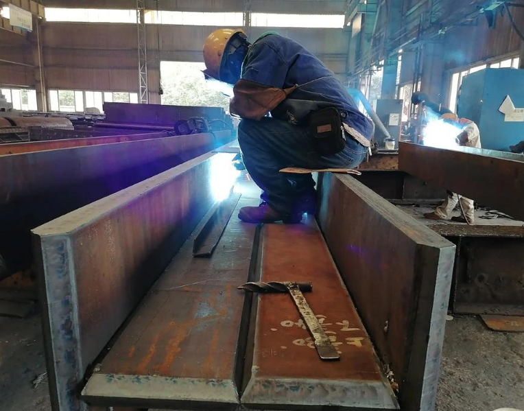
In the tank machining process, the outer wall of the tank is machined by bending the steel plate into an inverted U-shaped plate, and then turning the inverted U-shaped plate by 180° for subsequent machining steps. There is a certain height difference between the two working tables used for machining, which is normally handled manually or by means of a travelling crane, which is both time-consuming and labour-intensive.
Technology Enabling Elements:
A 180° workpiece turning device, which belongs to the scope of the present utility model, whose purpose is to lower or raise the height of a plate workpiece while improving the turning efficiency of the plate workpiece, and to provide safety and reliability during use.
The utility model adopts the workpiece 180 ° flip device, the purpose is to achieve the above content, it contains the clamping part, longitudinal beam, support column, base, right; clamping part of the upper part is equipped with a card with the kind of slots, slots opening direction horizontally forward, we must first remember that the clamping part is fixed in the longitudinal beam of the upper end of the position of the put, the longitudinal beam of the central part of the beam can be rotated in a certain way to install in the support column, here to pay attention to the support column is fixed above the base, right? The support column is fixed on top of the base, right, all clear.
The principle of operation is that the sheet workpiece is pushed horizontally into the slot, and then the longitudinal beam is rotated by 180°, so that the opening of the slot changes to the opposite direction of the original, and the height of the clamping section is raised or lowered, so that the sheet workpiece flips over during the rotation process, and the height of the sheet workpiece changes as well.
Further, there is included a limiting device for limiting the angle of rotation of said longitudinal beam.
More preferably, there are two clamping parts, which are set in parallel, said longitudinal beams and clamping parts are quantitatively compatible with each other, and the middle insides of the two longitudinal beams are secured to the ends of the same horizontal axis; the upper end of the said support column is provided with a sleeve which is compatible with the horizontal axis, and the said horizontal axis is rotatably inserted in this sleeve.
Further, said sleeve is provided with a bearing that mates with said horizontal shaft.
Firstly, it is preferred that the rear part of said clamping part is fixed to the upper end of said longitudinal beam, so that the centre of gravity of the clamping part is at the front side of the longitudinal beam; then, said limiting device comprises a first limiting crossbeam connected to the lower end of both said longitudinal beams, which first limiting crossbeam is in contact with the front side of said support columns and is limited by the support columns; and then, said limiting device comprises a second limiting crossbeam connected to the two clamping parts, which second limiting crossbeam meets the rear side of said support columns after 180° of the flip of said longitudinal beam and is limited by the support columns limiting crossbeam connecting two said clamping sections, this second limiting crossbeam being in contact with the rear side of said support column after said longitudinal beam has been turned over by 180°, and being limited by the support column.
In a further case, the support column consists of an upper support column which is firmly fixed to the upper part of the lower support column and which is fitted to the lower support column to form a concave table, in order to prevent the workpiece in the slot from colliding with the support column after the longitudinal beam has been turned over by 180°.

Further, said clamping section comprises an upper slide and a lower slide, the upper slide and the lower slide are provided in an upper and lower relative position, and a plurality of pulleys are mounted on the opposite side, one end of the upper slide and one end of the lower slide are connected and secured by means of a connecting plate, and it is the upper slide, the lower slide, and the connecting plate that cooperate with each other to form the said card slot.
Preferably, there are two said upper support posts.
Further, said support column is provided with a reinforcing plate at its connection with the base.
The structure of the device is simple, its operation is reliable, and can effectively prevent the workpiece in the process of turning to produce the phenomenon of bumping.
illustrate
Figure 1 is a schematic diagram of the side structure of the utility model;
Figure 2 is a left view of Figure 1;
Figure 3 is a side schematic diagram of the working state of the utility model;
Figure 4 is a left view of the utility model in Figure 3;
FIG. 5 is a side schematic view of the utility model in FIG. 3 after a 180° rotation;
Pictured:
1. A portion for clamping which includes an upper side slide numbered eleven, a lower side slide numbered twelve, a pulley numbered thirteen, a slot numbered fourteen, a connecting plate numbered fifteen, and a second limiting crossbar numbered sixteen.
2. longitudinal beam, 21. first limiting transverse beam, 22. horizontal axis;
3. There are parts called support columns, one of which is an upper support column numbered 31, and another is a lower support column numbered 32, and there is also a concave table numbered 33, and a sleeve numbered 34.
4. base, 41. reinforcing plate;
5. Front workbench;
6. Rear workbench;
7. Sheet workpieces.
practical way of doing sth.
The utility model is described herein in greater detail with respect to the accompanying drawings, and for ease of illustration, the left side of the inside of FIG. 1 is treated as the front, and the vertical paper face outward is treated as the left.
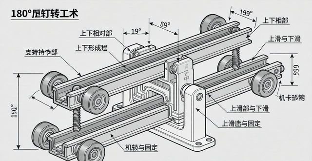
As shown in FIGS. 1 and 2, respectively, there exists a workpiece 180° turning device comprising a clamping section 1, a longitudinal beam 2, a support column 3, and a base 4; in the clamping section 1, a slot 14 is provided, and the opening direction of this slot 14 is horizontally forward, and the clamping section 1 is secured to the upper end of the longitudinal beam 2, and the middle portion of the longitudinal beam 2 is rotatably mounted on the support column 3, and the support column 3 is secured to the base 4. and the support column 3 is fixed to the base 4.
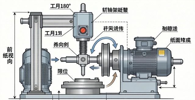
Principle of operation: In practice, in order to facilitate the use, the device is often used in conjunction with the front working table 5, and also with the rear working table 6, as shown in Figure 3. The front table 5 is on the side towards which the opening of the slot 14 is directed, and it is horizontally aligned with the slot 14, so that the sheet workpiece 7 can just be pushed into the slot 14 from the horizontal front table 5; the rear table 6 is on the other side, and when the longitudinal beam 2 is rotated by 180° in a clockwise direction, as shown in Fig. 5, the opening of the slot 14 turns into the opposite direction to the original one, and the rear table 6 is at the same level as the slot 14 at the same time as the slot 14. The rear table 6 is now on the same level as the slot 14, and the sheet workpiece 7 is pushed out of the slot 14, and the sheet workpiece 7 will go all the way directly onto the rear table 6. Since the height of the clamping section 1 decreases during the rotation of the clamping section 1 from the state in Fig. 3 to the state in Fig. 5, it is possible to meet the need for a reduced height of the workpieces to be processed. The plate workpiece 7 is turned over during the rotation process and its height is changed accordingly.
As an example of the process of processing the tank body, the U-shaped sheet workpiece 7 made of bent steel plate is placed upside down on the front table 5, and the bottom plate of the U-shaped sheet workpiece 7 is pushed into the slot 14, as shown in Figs. 3 and 4, and then turned over to work as shown in Fig. 5, and the opening of the U-shaped sheet workpiece 7 is directed upwards to enter the rear table 6 to carry out the next step of the production process.
To facilitate positioning of the longitudinal beam 2 and to be able to control the angle of rotation of the longitudinal beam 2, there is furthermore a limiting device for limiting the angle of rotation of the longitudinal beam 2. The limiting device can be a pin or other clamping member for rotational positioning, so that the present tilting device can be maintained in a stationary state as in FIG. 3, or in a stationary state as in FIG. 5, thus facilitating the entry or exit of the sheet workpiece 7 into or out of the clamping section 1.
In the preferred embodiment, as shown in FIG. 2, there are two clamping sections 1, which are set parallel to each other, and the longitudinal beams 2 are quantitatively matched with the clamping sections 1, and the middle insides of the two longitudinal beams 2 are fixed to the ends of the same horizontal axis 22, and the support column 3 is provided with a sleeve 34 at the upper end, which is fitted to the horizontal axis 22, and is rotatably inserted into the sleeve 34. The horizontal axis 22 is rotatably inserted into the sleeve 34; in such a structure, the support column 3 is on the inside of the two longitudinal beams 2, which prevents safety accidents such as pinching in the process of rotation.
In order to be able to make the rotation of the longitudinal beam 2 smoother and to avoid wear and tear of the horizontal axis 22 as well as of the sleeve 34; furthermore, the sleeve 34 is provided with an internal bearing that is mated with the horizontal axis 22.
Preferably, as shown in Figure 3, the rear part of the clamping part 1 is fixed to the upper end of the longitudinal beams 2, so that the centre of gravity of the clamping part 1 is at the front side of the longitudinal beams 2; the limiting device comprises a first limiting crossbeam 21 connected to the lower end of the two longitudinal beams 2, which is in contact with the front side of the support columns 3, and which is limited by the support columns 3; the limiting device also comprises a second limiting crossbeam 16 connected to the two clamping sections 1, this second limiting crossbeam 16 being in contact with the rear side of the support column 3 after the longitudinal beams 2 have been turned over by 180°, and also being limited by the support column 3. The design solution is structurally simple and not easily damaged.
In other words, in the initial state, as shown in FIG. 3, the centre of gravity of the clamping part 1 is in front of the longitudinal beam 2, so that the clamping part 1 and the longitudinal beam 2 have a tendency to rotate counterclockwise, and the lower end of the longitudinal beam 2 is fixed to the first limit crossbar 21, which is in contact with the front side of the lower support column 3, so that the tendency of the counterclockwise rotation of the clamping part 1 and the longitudinal beam 2 is blocked and the device is maintained in a stationary state as in FIG. 3. The device is maintained in a stationary state as shown in FIG. 3. The device is rotated in a clockwise direction, and when it is rotated to 180°, the situation as shown in FIG. 5 is presented, where the slot 14 is horizontally backward and the centre of gravity of the clamping part 1 is on the right side of the longitudinal beam 2, so that there is still a tendency for the clamping part 1 and the longitudinal beam 2 to rotate clockwise. In view of the fact that the second limit beam 16, which is fixed in the middle of the two clamping sections 1, is in contact with the rear side of the support column 3, the second limit beam 16 prevents the clamping section 1 and the longitudinal beam 2 from continuing to rotate clockwise, so that the device remains in a stationary state as in FIG. 5.
If the support column 3 is set vertically, the edge of the sheet workpiece 7 will first touch the rear surface of the support column 3 during the rotation of the clamping section 1 from FIG. 3 to FIG. 5, and the support column 3 will push the sheet workpiece 7 out of the groove 14 when the rotation is continued, which may easily cause damage to the sheet workpiece 7. Therefore, as a further improvement, as shown in FIGS. 3 and 4. The support column 3 comprises an upper support column 31 and a lower support column 32, the upper support column 31 is fixed to the upper end of the lower support column 32 and cooperates with the lower support column 32 to form a concave table 33, which has a rearward opening as shown in FIG. 5, in order to prevent the workpieces in the groove 14 and the support column 3 from colliding with the support column 3 after the longitudinal beam 2 is turned over by 180°.
In order to easily push the sheet workpiece 7 into or out of the slot 14, furthermore, the clamping section 1 contains an upper slide 11 and a lower slide 12, the upper slide 11 and the lower slide 12 are set opposite each other, and a plurality of pulleys 13 are mounted on the opposite side, and the upper slide 11 and the lower slide 12 are connected at one end by means of a connecting plate 15, and are held in place. The upper slide 11, the lower slide 12 and the connecting plate 15 cooperate with each other to form a slot 14, and the plate workpiece 7 is in direct contact with the pulleys 13, so it can be easily pushed.
In order to make the support of the support columns 3 against the horizontal axis 22 more stable, it is preferred that there are two upper support columns 31, as shown in FIGS. 2 and 4; this being the case, the sleeve 34 will also be provided with two corresponding sleeves, thus making the rotation of the longitudinal beam 2 more stable.
In the case shown in FIGS. 1 to 5, in order to strengthen the connection between the support column 3 and the base 4, furthermore, a reinforcement plate 41 is provided where the support column 3 and the base 4 are connected.
This device is simple in structure, reliable in operation, and can effectively prevent the phenomenon of workpiece knocking in the process of turning.


No comments