

The basic principle is that the teeth of two gears mesh with each other to transmit motion and power, for involute gears, its instantaneous transmission ratio should be a constant in theory, however, the precision error will cause damage to this ideal state, the accuracy of the gear characteristics are mainly in the movement accuracy, contact accuracy, smoothness of the three aspects of the embodiment:
Motion accuracy is the deviation between the actual ratio and the theoretical ratio of the gear in the transmission process.
In a power transmission system, high precision motion transfer activities are the key to ensuring the stability and reliability of the mechanical system. Deviations in motion accuracy can lead to changes in transmission ratios, increased wear on the tooth surfaces, vibration and noise, and in severe cases, even affect the overall performance of the system.
What is contact accuracy? It describes the contact condition between the gear teeth, which covers the contact area, the contact pressure, and the form of contact.
Contact accuracy is good, can ensure that the gear in the transmission process, have a uniform load distribution, as well as have a high bearing capacity, and thus.
Extends the life of the gears.
Smoothness is about the smoothness of the gears in the transmission process, that is, the shock and vibration condition of the gears at the time of meshing.
The smoothness accuracy of gears is affected by a variety of factors, including tooth pitch deviation, tooth shape error, and base pitch deviation. Gear transmission, the requirement of instantaneous speed ratio changes in the design range, smoothness accuracy is improved, can effectively reduce the transmission process generated by the vibration shock and noise and so on, and thus improve the reliability of the system and comfort.
Main items for precision control
Cylindrical gears mesh with each other in a point contact mesh situation in the height dimension of the gears, which is judged as a tooth shape error; however, in the direction of the tooth length of the gears, a line contact mesh situation is shown, which is judged as a tooth direction error.
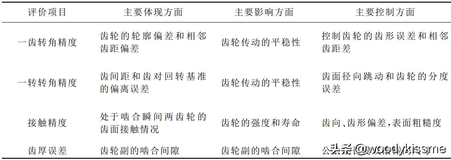
The main purpose of evaluating the angle error of one tooth is to determine the smoothness of the contact at the moment when the gear pair meshes. Since the gear pair has a large tooth backlash, this is a kind of floating contact, which is mainly detected by the tooth shape error and the difference of the neighbouring tooth pitch. If the tooth shape error and neighbouring tooth pitch difference are excessive, it will lead to a large change in the contact stress on the tooth surface, which will result in a shock contact of the gear pair during the meshing process.
Influencing factors:
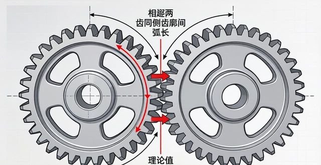
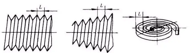
Individual tooth pitch deviation, is the actual tooth pitch of a single tooth, that is, the arc length between two adjacent teeth on the same side of the tooth profile, to go with the theoretical tooth pitch subtracted from the resulting difference. Tooth shape error, is the actual tooth profile shape deviation to the degree of the theoretical involute, that is, the total tooth profile deviation. Even if the tooth pitch is the same, but the tooth shape is not good, it will lead to changes in the position of the meshing point, thus causing fluctuations in the angle of rotation. The base pitch deviation is the difference between the actual and theoretical values of the base pitch, which directly affects the interference or clearance between the two gear teeth at the point of meshing in and out, causing impacts and sudden changes in the corner.
The standard is rated by ±f_i', a one-tooth tangential composite deviation, or its angular representation.
The main purpose of evaluating the accuracy of the angle of rotation is to identify the deviation from the error on the occasion of gear rotation, and to ensure that the radial runout of the tooth surface and the indexing error of the gear are ensured.
Influencing factors:
For the cumulative total deviation of tooth pitch, it refers to the difference between the actual arc length corresponding to any K tooth pitches and the theoretical arc length on the gear indexing circle, and the maximum absolute value of this difference is the cumulative total deviation of tooth pitch. It is one of the most important factors that can reflect the cumulative effect of uneven distribution of pitch within a circle. Geometric eccentricity is a condition in which the centre of rotation of the gear, i.e. the centre of the reference bore, and the centre of the indexing circle do not coincide when the gear is machined or mounted. Motion eccentricity refers to cyclical machining errors caused by a number of factors such as eccentricity of the machine's indexing worm gear or workpiece installation. Radial runout is the radial offset of the ring relative to the axis of rotation, which is usually caused by geometric eccentricity.
With a one-sided mesh checker, i.e. a single mesh instrument to measure F_i', that is, the total tangential deviation ah, which is a comprehensive indicator of the full presentation of the accuracy of a turn, which covers the cumulative tooth pitch, tooth shape, the base of the joints, and so on, the comprehensive impact of the errors brought about by the.
Evaluation of the contact accuracy of gears is mainly to judge the contact condition of the tooth surface when the two gears are in the moment of meshing. During the meshing transmission of the gear pair, the actual contact spot on the tooth surface area size, shape and location of the theoretical contact area with the degree of conformity. It reflects the ability of the gear pair load distribution uniformity.
Influencing factors:
Toothedness error refers to the extent to which the actual toothed line, i.e. the profile in the direction of tooth length, deviates from the theoretical toothed line, involving total toothedness deviation, helical line error, etc., which is the key to the impact on the length of the contact line. Axis parallelism error indicates that the axes of the two meshing gears are not parallel in space, and there is an angle or offset phenomenon. Form error affects the position of the contact point in the tooth height direction. Pitch errors affect the distribution of contact points in the tooth direction. The deviation of the centre distance of the box hole and the axis skew are errors that occur during assembly. Shafts and bearings have deformations and clearances.
The most commonly used and intuitive method is the static contact spot check, i.e. the colouring method, but of course there are also cases where the measurement is reversed and modelled and then analysed.
Gear tooth thickness is determined by measuring the length of the common normal or the dimension of the pitch across the bar, which is converted to ensure that the mesh clearance of the gear pair is guaranteed. The backlash of the gear pair is related to the centre distance, the tooth thickness and the runout of the tooth flanks when the gears are installed.
Influencing factors:
During the machining process, the depth of feed of the tool, as well as the wear of the tool. After heat treatment, deformation occurs, which usually results in a thinning of the tooth thickness.
Specifying the permissible range of variation of tooth thickness is done in the standard by using E_sn (upper deviation of tooth thickness), or by using E_sni (lower deviation of tooth thickness), or by using T_sn (tolerance of tooth thickness).
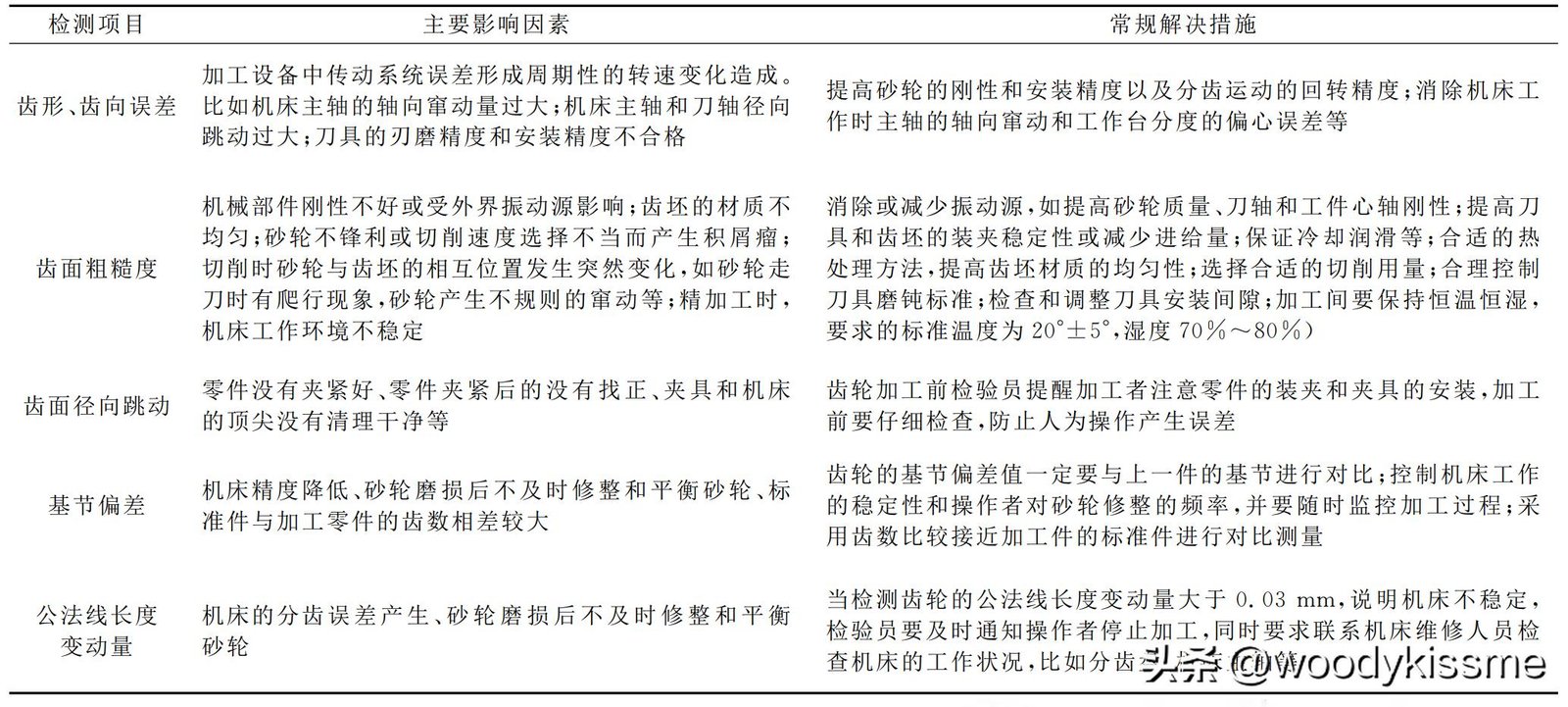
The next to be found in this way, for a brief nature, about the gear testing project, the sources of error and solution measures related to the content of the table, if there are some inappropriate places, welcome to give criticism and corrections.
I, in such a situation, am regularly engaged in sharing content related to mechanical transmission and then gear processing, for the group of friends who are interested in the same category, can choose to pay attention to my behaviour. With such a desire in my heart, I hope to be able to participate in discussions with you around this situation!
The design of gears, the machining of gears, the design of tools to be used in the machining of gears, the manufacturing of tools, and the use of tools are all relevant issues.
That's all I have to share today, thank you for taking your precious time to read!
Past Highlights:
"Linking" two involute splines requires a common hob".
Correlation between gear errors "Link".
"Why are involute gears still standing?".


No comments