
aerospacecomponentprecision machiningprocess plan
As a process engineer who has been committed to technical research in the field of precision machining for many years, I have been involved in many high-precision work projects over the past ten years, such as the breakthrough in the processing of turbine discs for aero-engines, the exquisite forging of structural parts for spacecraft, and the fine sharpening of the satellite payload bracket. Every time I look at the design drawings on the kind of “± 0.005mm” extremely strict shape and position tolerance requirements, or “Ra0.2μm” this kind of technically challenging surface roughness marking, the heart can be strongly experienced: precision machining of aerospace parts! We can strongly feel that the precision machining of aerospace parts is not only a technical competition, but also an ultra-precision battle with “micron as the measuring scale, temperature as the object of confrontation, and vibration as the attacking edge”. In the future, I will combine the project experience with the actual work, and systematically compile a set of solutions for the precision machining process suitable for the aerospace industry.
I. Programme background and targeting
1.1 Industry Demand Drivers
Far beyond the requirements of the conventional mechanical field, aerospace equipment on parts and components have the reliability, lightweight and long life requirements, take a certain type of turbofan engine compressor blade as an example of this is one, it needs to go to withstand the complex stress, in the high temperature of 1,500 ℃ as well as 30,000 rpm under the conditions of very high speed, and secondly, any small processing defects, such as knife marks, residual stress concentration, such cases are very likely to cause fatigue fracture problems, which in turn lead to the failure of the whole machine. These situations are very likely to cause fatigue fracture problems, which will lead to the failure of the whole machine. Thirdly, spacecraft structural components are subjected to an overload of more than 20g at the time of launch, and fourthly, if the processing precision is insufficient, the assembly stress will be triggered, which will affect the on-orbit attitude control, and these scenarios, in turn, force the machining process to have to be “sub-micrometer precision” and “nanometer precision”. These scenarios in turn force the machining process to break through the technical barriers of "sub-micron precision" and "nanometre surface quality".
1.2 Core objectives of the programme
Focusing the programme on typical aerospace components, such as titanium alloy structural parts, high-temperature alloy turbine discs and aluminium alloy satellite mounts, the goal is to build a precision machining system that is “material - process - equipment - testing” synergistic. The goal is to build a precision machining system that is "material - process - equipment - testing" synergistic, to be realised:
Dimensional accuracy: key feature tolerances are controlled within ±0.003mm;
Surface quality: Ra≤0.2μm (Ra≤0.1μm for some functional surfaces);
Consistency: Fluctuation of key dimensions of the same batch of parts ≤ 0.002mm;
Efficiency Improvement: Reduction of single-piece machining time by 20% or more through process optimisation.
II. Design of core modules for the Set Art programme
2.1Material propertiesProcess suitability analysis
The machining characteristics of titanium alloy TC4, a material commonly used for aerospace parts, nickel-based high-temperature alloys, a material commonly used for aerospace parts, and aluminium alloy 2A14, a material commonly used for aerospace parts, are extremely different, and process routes need to be designed to address their respective characteristics.
Take my participation in a certain type of satellite load bracket, the material is TC4 titanium alloy, this titanium alloy thermal conductivity is poor, only one-fifth of 45 steel, it is chemically active, easy to bond with the tool, it is low modulus of elasticity, easy to rebound when machining, resulting in the size of the super poor. In the initial trial machining, we have chosen a conventional carbide tool, the situation is that the tool life is only 3 pieces per edge, and the machining surface shows obvious “scales”; and then replaced with a coated tool, that is, the kind of TiAlN coating, but also reduce the cutting speed from 80m/min to 50m/min, and at the same time increase the cutting speed to 50m/min, and at the same time increase the cutting speed to 50m/min. / min, and at the same time increase the coolant flow, the use of internal cooling tool, the pressure of 8MPa, so as to improve the tool life to 20 pieces per edge, surface roughness from Ra0.8μm stable to Ra0.4μm.
Another example is high-temperature alloys, which contain a large number of Ni elements, but also contains Cr, Mo and many other elements, in the processing time, the depth of its hardened layer can reach 0.3mm, while the ordinary steel is only 0.1mm.
In the future, with the development of aerospace equipment in the direction of “lighter, stronger and smarter”, precision machining will encounter new challenges, such as the processing of carbon fibre composite materials, and the manufacture of micro-nano structures. However, I firmly believe that as long as we uphold the “excellence” such a craftsmanship, adhere to the “data speak” such a scientific attitude, we will be able to precision machining on this track, to China's aerospace industry to support a more solid! “industrial foundation”.
Operator error, the risk of presenting the machining programme call is wrong, the tool clamping is not up to the appropriate position. Countermeasures: the implementation of the “two-person review system”, that is, after the operator enters the parameters, the technician again for verification, and in the machine tool operating panel to set the “anti-dumbing prompts”, such as not clamping the tool when the screen flashes red warning.
IV. Summary and outlook
In more than a decade of practice, I have witnessed a shift from “experience-driven” to “data-driven” aerospace precision machining. The key point of this programme is the deep integration of material properties, equipment performance and inspection methods, with the concept of “micron-level precision” running through every machining step. Recalling last year's participation in the processing of critical structural parts for a certain rocket, we adjusted the position of the fixture support point seven times, measuring more than 200 sets of data, in order to improve the position of a hole from ±0.005mm to ±0.003mm, and eventually the parts were launched smoothly along with the rocket, and we felt a strong sense of achievement that we had not failed to live up to our entrusted task. “When the final part was successfully launched with the rocket, the strong sense of achievement that I felt was more precious than any other reward.
Vibration suppression, the use of “modal analysis” technology, for the tool - shank - spindle system to carry out frequency response function test, to avoid the intrinsic frequency of the part, such as a bracket intrinsic frequency is 800Hz, when machining the spindle speed adjusted to avoid the 800Hz When machining, the spindle speed is adjusted to avoid multiples of 800Hz, for example, / min corresponds to 300Hz, and at the same time using vibration-damping toolholder, which has a built-in damper that can reduce the vibration amplitude of 60%.
(3) Supplementary speciality processing technologies
For tiny features that conventional cutting has no way to deal with, such as cooling holes with a diameter of 0.3mm and narrow grooves with a depth-to-width ratio of 15:1, special processes such as EDM and laser machining should be introduced. For example, a certain type of combustion chamber nozzle has micron-sized cooling holes with a diameter of 0.2mm and a depth of 3mm, which are processed by an EDM small hole machine. Through the optimisation of the pulse parameters, the voltage is about 80V, the current is about 2A, and the pulse width is 5μs, and the thickness of the remelted layer of the hole wall is controlled to be less than 5μm, while it can be up to 20μm under the conventional parameters, which can avoid the risk of cracks caused by the remelted layer.
Tool wear is extremely fast. When we machined the turbine disc tongue and groove, because we did not consider the hardening characteristics of the material, after the first piece of machining was completed, the tool rear face wear reached 0.3mm, exceeding the tolerance by 0.2mm, resulting in the second piece of the size of the excessively poor. In the subsequent optimisation process, we distinguish roughing and finishing, roughing the use of ceramic tools, its high hardness and wear resistance, cutting depth of 1.5mm, finishing the use of PCBN tools, that is, Cubic Boron Nitride, high temperature, cutting depth of 0.3mm, and add 30 minutes of natural aging between processes, so as to release cutting stress, and ultimately the size of the unstable problem to be solved.
In-line measurement, the machining centre incorporates a touch-trigger probe, Renishaw's OMP60, which automatically aligns the workpiece prior to fine machining, with a repeatability of ±0.001mm, to avoid batch overruns due to clamping offsets.
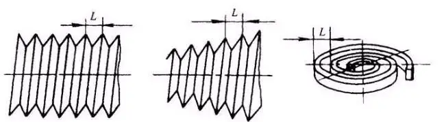
After the completion of parts to do final inspection traceability, this time to use high-precision coordinate measuring machine to do full-size inspection, the accuracy of this measuring machine is 0.5μm + L/1000, the measurement data will be automatically uploaded to the MES system, these data will be correlated with the process parameters, process parameters include tool type, cutting parameters, machining time, etc., in this way can be achieved.“ A part of an electronic resume”, which is very convenient for subsequent quality problems traceability.
III. Programme implementation and risk control
3.1 Phased implementation plan
This programme needs to be advanced in accordance with three phases, which are process validation, small batch trial production, and batch stable production:
Phase 1 (1 to 2 months), which is a process validation phase, involves selecting two to three typical parts, like turbine blades and satellite mounts, and applying the orthogonal test method, or L9(3⁴), to optimise the cutting parameters, including spindle speed, feed, depth of cut, and coolant pressure. In this way, the optimum process combination is determined and the reliability of fixtures and inspection methods is verified.
(2) Full-process testing and error traceability
“Controllable” is the core of precision machining, but the inspection is the “control” of the eyes, we built up a set of three inspection system, which includes process self-inspection, but also covers the online measurement, and there is a final inspection traceability.
In the machining process, whenever a process is completed, such as rough milling, and semi-finish milling, it is necessary to use a portable coordinate measuring machine, that is, Hexagon, for key dimensions, such as the positioning hole spacing, to carry out a rapid measurement, a single measurement time should be less than or equal to 2 minutes, once exceeded the value of the tool compensation should be adjusted immediately.
3.2 Key Risk Points and Responses
The risk of abnormal tool wear is a steep deterioration in surface roughness and out-of-tolerance dimensions. The response is to equip the tool shank with a vibration sensor with a sampling frequency of 10kHz to monitor in real time the fluctuation of the cutting force, with a normal fluctuation range of ±5%, and if the fluctuation is more than 10%, the tool will be automatically stopped and replaced.
The risk of uncontrolled thermal deformation is the presence of dimensional deviations in different positions of the same part, for example, a part machined in the morning is smaller by 0.003mm than in the afternoon, and the response to this is for the workshop to be thermostatically controlled, with a temperature range of 20 ± 0.5°C, and to add a 1 hour “warm-up programme” after the machine is started up. The response was to set the temperature range to 20±0.5°C, and to add a 1-hour "warm-up programme" after machine start-up, i.e. idling the spindle and moving the axes, to ensure that the machine reaches thermal balance.
2.3 Design of jigs and fixtures and inspection system
(1) Highly rigid fixture design
Most of the aerospace parts are thin-walled and weakly rigid structures, and the fixture design should follow the principle of “minimum constraint and uniform force”. We have designed a “vacuum adsorption + flexible support” fixture for a certain type of spacecraft support. There are dense vacuum holes on the base plate with a spacing of 5mm, and the workpiece is adsorbed with the help of a vacuum pump, and the adsorption force is 50N/cm². At the same time, in the weak points of the workpiece, such as the root of the reinforcing bar, set the elastic support block, polyurethane material, the hardness of Shore A70, which not only prevents the traditional mechanical clamping jaws to appear local indentation, but also control the clamping deformation within 0.001mm.
(2) Microvibration suppression and thermal deformation control
In precision machining, “heat” and “vibration” are two major “invisible killers”. Take the machining of aluminium alloy case as an example (the wall thickness of this case is 2mm), the cutting heat can cause the local temperature of the part to rise by more than 50℃, and the thermal expansion can reach 0.01mm (the coefficient of linear expansion of aluminium alloy is about 23×10-⁶/℃). The solution we have adopted is:
Temperature control, the spindle part of the machine tool is installed with infrared temperature sensors, which can monitor the temperature in real time, with an accuracy of plus or minus 5 degrees Celsius, and at the same time, the infrared temperature sensors are also installed on the workpiece fixture to monitor the temperature in real time, with an accuracy of plus or minus 5 degrees Celsius, and the machine tool numerical control system is used to call the thermal error compensation programme, which is built up in advance with the help of laser This thermal error compensation procedure is in advance with the help of laser interferometer to measure the thermal deformation curve of the machine tool at different temperatures after the establishment of the compensation model.
2.2 Core machining process selection and parameter optimisation
(1) High-speed cutting and five-axis linkage technology
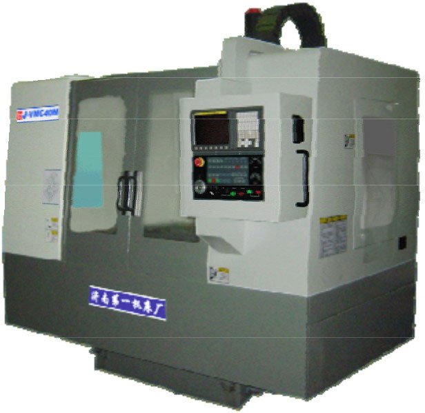
Many aerospace parts are complex curved surfaces, such as blades and impellers, and traditional three-axis machining requires multiple clamping, with an accumulated error of more than 0.01mm. Our team, in the processing of a certain type of engine deflector blade, the introduction of five-axis linkage machining centre, that is, Dermagit, with the help of “a clamping, multi-face machining”, the clamping error from 0.008mm to 0.002mm. at the same time, the use of high-speed cutting mode, its rotational speed per minute for units, feed rate is also per minute for units, the same feed rate is per minute for units. At the same time, the high-speed cutting method, with a rotational speed in units per minute and a feed rate in units per minute, reduces the cutting force with the help of the “adiabatic shear effect”, which reduces the cutting force by 30% compared with the conventional cutting method, thus avoiding the situation of a thin-walled blade, which has a thinnest point of 1.2mm, and will not be subjected to the stresses and deformations that result in the deviation of the profiles.
Small batch trial production stage, the length of 1 month, this stage should be put into 10 to 20 pieces of products for production, and focus on the three indicators to be monitored, these three indicators are “dimensional consistency”, and “tool life,” and “machining efficiency” situation, if a delivery pass rate greater than or equal to 98%, and tool life to meet the standard requirements, such as titanium alloy machining tool life to be greater than or equal to 20 per edge to meet the standard, then you can enter mass production.
In this stage of batch stable production, to establish “process parameters SOP file”, establish “equipment maintenance schedule”, establish “inspection frequency list”, and to regularly carry out To carry out regular process review of this work, the cycle is once a quarter, but also based on production data to optimise the process, for example, such as tool wear can be automatically adjusted to compensate for the value.


No comments