
“Chapter 5 Machining Quality of Workpieces”, has been shared by members and can be read online, more related to “Chapter 5 Machining Quality of Workpieces (56 pages)”, may be searched there in Vegetarian Library!
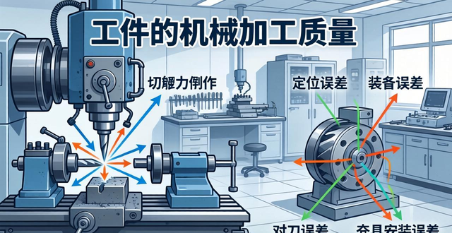
1, Chapter 5, the quality of machining of the workpiece, the main points of this chapter, there are the basic concepts of machining quality, and the impact ofmachining accuracyand the factors that influencesurface qualityFactors. Section 1, the basic concepts of machining quality, chapter 5 the machining quality of the workpiece, a, the concept of machining quality, the machining quality of the workpiece covers two aspects, that is, machining accuracy as well as surface quality. Machining accuracy and machining error, the actual geometric parameters of the surface of the workpiece after machining, size, shape, and mutual position, and the degree of conformity with the ideal value is called machining accuracy, and the degree of deviation from the ideal value is called machining error. Machining accuracy and machining error is from the opposite two aspects to describe the geometric parameters of the workpiece, machining accuracy is high, then the machining error is small, and vice versa, the machining error is large, then the machining accuracy is low. The content of machining accuracy and machining error contains dimensional accuracy, or error, shape accuracy, or error, positional accuracy, or error. Machining surface quality surface.
2. Geometrical characteristics, that is to say, the micro-geometry of the surface, covering surface roughness and waviness. Surface layer material changes, refers to the surface layer appears, and the matrix material organisation is not the same as the deterioration, including cold work hardening, metallurgical organisation changes, residual stress. Chapter 5 the machining quality of the workpiece 4 two, the method of obtaining machining accuracy and economic machining accuracy, the method of obtaining dimensional accuracy, test cutting method, the position of the tool relative to the workpiece, is carried out repeatedly by the test cutting, measurement, adjustment, and then test cutting and can be determined, the method is characterised by the productivity is low, the accuracy is dependent on the level of the workers, so it is suitable for the single piece of small batch production. Adjustment method, workpiece processing before the pre-adjustment of the relative position of the tool and the workpiece on the machine tool, and in the process of processing to maintain the position constant, the method is characterised by high productivity, good dimensional stability, suitable for mass production. Chapter V Machining Quality of Workpieces 5, fixed-size tool method, with the help of the size of the tool to ensure that the size of the workpiece.
3, such as hole machining, groove machining, etc., the characteristics of the workpiece size accuracy depends on the accuracy of the tool size, automatic control method, with the help of measuring devices, feeding devices and control systems, so that the workpiece in the machining process of their own measurement, feeding, compensation, and thus achieve the required size, the characteristics of the method is high precision machining, high productivity, and is suitable for use in automated machine tools for machining, the method of obtaining the shape of the accuracy of the method of the track The cutting movement by virtue of the cutting tool tip trajectory to shape the shape of the surface of the workpiece being machined, forming method, the use of the geometry of the cutting edge of the forming tool cutting the shape of the workpiece, Chapter 5, the quality of machining of the workpiece, 6 exhibition method, the use of the tool and the workpiece for the exhibition of the movement of the occasion, the cutting edge in the surface of the formation of the envelope on the surface of the workpiece constitutes the surface of the workpiece being machined, the phase tangent method, the use of rotating tools, such as milling cutters, the cutting edge of the cutting tool, the cutting edge of the cutting tool, the cutting edge of the cutting tool, the cutting surface of the workpiece. When cutting, the envelope of the cutting edge trajectory forms the machined surface of the workpiece, Chapter 5 Machining quality of the workpiece, 7 to obtain the position.
4, in the workpiece processing, to obtain the positional accuracy of the method, mainly depends on the workpiece clamping method, which mainly has a positive clamping method and special fixture clamping method. The economic accuracy and economic surface roughness refers to, a certain processing method in normal production conditions, the use of quality standards in line with the equipment, process equipment and standard technical level of workers, and does not extend the processing time, the machining accuracy can be achieved, which also covers the economic surface roughness, which can be referred to the relevant manuals. It should not be understood as a definite value, but rather as a range of accuracy. The various economic machining accuracies are not static and will increase as the level of machining technology improves. The accuracy and surface roughness in the relevant manuals and literature refer to the economic accuracy and economic surface roughness. Chapter 5 the machining quality of the workpiece 8 a. affect the machining accuracy of the original error and classification, machining process system, in the machining process, by the machine tool, workpiece, fixture and tooling composed of a closed system called.
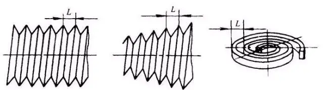
5, for the machining process system, chapter 5 is the machining quality of the workpiece, the second section of the factors affecting the machining accuracy, which 9 mentioned the process system of the original error, caused by machining error is the fundamental cause of the process system there is an error in the process system, the process system of the error is called the original error, which includes the original error composition as well as the original error of the classification of the workpiece of chapter 5 of the machining quality of the workpiece in the 10, two is the Machining principle error, machining principle error refers to the error caused by the use of approximate shaping motion or approximate cutting edge profile for processing, such as in the CNC milling machine with a ball-end cutter milling complex shaped parts, see Figure, where R is the radius of the ball-end cutter, h is the permissible height of the residue, rolling and cutting of involute gears with an Archimedean worm hob, metric screw turning worm or inch threads, because of the use of approximate Forming motion or approximate cutting edge profile, often can simplify the machine structure or tool shape, or can improve productivity, and sometimes can get high machining accuracy, so it is widely used in production.
6, with the prerequisite that the principle error does not exceed the specified accuracy requirements, which have a specific standard. Usually the principle error does not exceed 10, 15 and workpiece tolerances, which is the case in chapter 5 under the machining quality of the workpiece. Among them, 11, 3 related to machine tool geometric error and its impact on machining accuracy, machine tool geometric error is presented as the machine tool guideway error, spindle rotation error, etc., which is generated by the machine tool itself, manufacturing errors, installation errors and wear and tear, which is also based on the quality of machining of the workpiece in chapter five. Machine guideway error, lathe guideway in the horizontal plane there is straightness error x, lathe guideway in the vertical plane there is straightness error y, which also belongs to the fifth chapter of the workpiece machining quality category. The tip of the tool is displaced relative to the tangent direction of the workpiece rotary axis on the machining surface, which is the non-sensitive direction of the machining error, and the displacement is equivalent to the straightness error of the guideway, and the trajectory of the tip of the tool in the horizontal plane is not a straight line, which in turn results in the axial shape error of the workpiece and the cylindricity error. In addition, the lathe front and rear guideway distortion n, which is still the fifth chapter of the work of the relevant content.
7, Chapter 5, the machining quality of the workpiece, the table in motion will produce oscillation, the tip of the tool movement trajectory is a space curve, which in turn produces processing errors, such as cylindricity error, like the lathe HB23n this has a great impact on the lathe longitudinal guide and the spindle in the horizontal plane there is a parallelism error and make the workpiece produces a cylindricity error, if the lathe guide and the spindle parallelism error of Hx, L, tan. Then the workpiece diameter error d is 2Hx, 2L, tan, lathe longitudinal guide and spindle in the vertical plane with parallelism error will appear saddle, axis profile in the hyperbola, for example, lathe guide and spindle parallelism error of Hy, L, tan, there will be workpiece diameter difference, lathe horizontal guide and spindle axis with perpendicularity error, the horizontal guide and the spindle angle of n f, which will lead to the plane.
8, degree error d, 2 times tan17, machine tool spindle rotation error, contains pure axial runout, pure radial movement and pure angular oscillation, Chapter 5 elaborates on the machining quality of workpieces,18, IV, tool manufacturing error and wear, fixed-size tools, like drills, reamers, keyway milling cutters, floating boring blocks, broach cutters, etc., the size and shape error and wear, will directly involve the dimensional accuracy of the workpiece and the shape accuracy, the shape error and wear of forming tools and spreading tools will directly involve the shape accuracy of the workpiece, ordinary tools, such as ordinary turning tools, planer tools, face milling cutters, single-edged boring cutters, etc., their manufacturing errors and machining accuracy do not have a direct correlation, however, their wear has a great impact on the size and shape accuracy of the workpiece, Chapter 5 Machining quality of the workpiece, the effect of lathe tool back face wear on the The effect of machining dimensions, the specific process of tool wear, 19, Chapter 5 Machining Quality of Workpieces, V, Fixture Manufacturing Errors and Wear, Positioning Errors, Tool Guidance, Tool Setting Errors, Clamping Errors, Fixture Security.

9, mounting error 1, usually requires positioning error is not greater than the corresponding workpiece size tolerance of 1 / 3, 2, tool setting error and fixture installation error and not greater than the corresponding workpiece size tolerance of 1 / 3, 20, six, the process system force, heat deformation caused by the error, Chapter 5, the machining quality of the workpiece, the process system stiffness, the process system is subjected to deformation caused by machining error, the definition, the process system Stiffness refers to the process system in the cutting force Ff, Fp, Fc under the combined effect of the machining surface normal direction of the cutting component force Fp and the tool in this direction of the relative displacement y ratio, that is, the formula Js process system stiffness, Fp eating knife resistance, cutting force normal component force, y process system displacement, cutting the combined effect of the displacement of the force, 21, the formula Js process system stiffness, Jjc machine tool stiffness , Jjj fixture stiffness, Jdj tool holder stiffness, Jg workpiece stiffness, process system force deformation and so on.
10, for the process system components of the force deformation of the iteration of this situation, which can be derived from the process system stiffness and process system components of the relationship between the stiffness of the relevant formula, which is the process system stiffness calculation instructions. For the workpiece, the shape of the tool holder is simple, its stiffness can be used to calculate the mechanics of materials formula, and for machine tool components, fixtures, etc., most of the stiffness of the experimental method to determine. In the above formula for the calculation can be appropriate to partially simplify the deformation of the small part of the neglect. Chapter 5 of the workpiece machining quality of 22, the stiffness of the machine tool components can be determined with the help of experiments, based on the workpiece processing conditions can be calculated by the stiffness of the machine tool. In terms of lathe turning short rough optical axis, the stiffness of the machine tool and its impact on machining accuracy, in Chapter 5, the quality of workpiece machining in the conclusion. Firstly, the stiffness of the machine tool is not a fixed value, but a function of the position of the turning tool, so that the diameter of the workpiece in the axial direction will not be uniform because of the effect of the elastic deformation of the process system. Secondly, it is possible to find out separately for each particular position of the machine tool.
11, stiffness, such as the formula 3, 5, 3, 6, 3, 7 and 3, 8, where, in general, the tool is located in the workpiece at the midpoint of the stiffness of the machine tool on behalf of the stiffness of the machine tool, i.e., 23, the stiffness of the workpiece and its impact on the machining accuracy, in some machining conditions, compared with the other components of the process system, the deformation of the workpiece is the main, at this time the workpiece's stiffness is the main cause of the influence of the workpiece machining accuracy, the workpiece Specific deformation of its clamping method, the workpiece on the lathe with two top clamping, workpiece on the lathe with chuck clamping, chapter 5, the machining quality of the workpiece, two top clamping, chuck clamping, 24, thin-walled workpiece clamping on the chuck, thin plate workpiece on the workbench with electromagnetic clamping, chapter 5, the machining quality of the workpiece, thin-walled workpiece grinding, 25, tool stiffness and its impact on the machining accuracy of the Influence, When boring on a horizontal boring machine, the influence of tool stiffness on the machining accuracy of the workpiece is the main factor, Tool stiffness includes spindle stiffness and tool.
12, boring machine spindle rod stiffness, in all directions is not the same, when the spindle overhang length is greater, then the lower the stiffness, and different directions of the stiffness of the difference is smaller, because the boring when the cutting direction is changed, so it will produce roundness error, the boring way there are two kinds of boring, a kind of table does not move, the boring bar for feeding, so that in addition to the hole cross-section is not round in addition to the axial cross-section diameter The other is the table feed, the boring bar suspension length remains unchanged, the hole cross-section is not round, but the axial cross-section of the diameter is the same, Chapter 5 talks about the quality of machining of the workpiece, the different ways of boring, 26 is the law of error reenactment, the fifth chapter of the quality of machining of the workpiece, is an elliptical cross-section turning as an example for the illustration of the 27 error reenactment can be expressed in terms of error reenactment coefficient, error reenactment Coefficient of error reflection can be expressed by the coefficient of error reflection, the coefficient of error reflection is inversely proportional to the stiffness of the system, it can be derived from the previous formula, in machining, the coefficient of error reflection is usually less than 1, can be eliminated by multiple tool travel, the effect of error reflection, from the above analysis can be known, the blank of the workpiece exists in the shape of the error.
13, batch production in the adjustment method of processing a batch of workpieces, if the diameter of the blank is not the same size, or hardness is not uniform, when there is a difference or mutual positional errors, the processing of the same kind of machining errors will occur, the same will be similar to happen. Chapter 5 the machining quality of the workpiece, 28 to improve the stiffness of the process system of the main measures are, improve the stiffness of machine tools and fixtures, reasonable design of parts structure and cross-sectional shape, minimise the number of parts composed of components, as a way to reduce the total contact deformation, the use of pre-tensioning measures in the assembly, the fifth chapter of the quality of machining of the workpiece, the closed overall box structure.29 to improve the stiffness of the workpiece when machining, Chapter 5 Machining quality of workpieces, special jaws, open transition ring, the use of special jaws or open transition ring, can make the clamping force uniform, reduce the clamping deformation.30 Improve the stiffness of the tool machining, Chapter 5 Machining quality of workpieces, hole machining tools, drills, reamers, boring tools, in the use of the tool, by adding additional support.
14. drilling bushings and boring bushings, used to improve tool rigidity, 31. thermal deformation exists in the process system and its impact on machining accuracy, the process system has a heat source, chapter 5 on the quality of machining of workpieces, thermal deformation of the machine tool can cause machining errors, which is characterised by a huge volume, a huge heat capacity, a temperature rise that is not very high, a long time required to reach thermal equilibrium, a complicated structure, a temperature field and a deformation that is uneven, the impact on machining accuracy is quite significant. The impact on machining accuracy is quite significant, thermal deformation of machine tools related examples, 32. Chapter 5 on the quality of machining of the workpiece, a. the deformation pattern of the lathe after heat, b. temperature rise and deformation curves, a. deformation pattern of the milling machine subjected to heat, c. the deformation pattern of the guideway grinder after heat, 33. cylindrical workpiece thermal deformation, the workpiece suffers from the uniform heat, the cumulative error of the 5th level screw in the full length of 5m In this case, L and D represent the length and diameter and the amount of thermal deformation, respectively. L and D are the original length and diameter of the workpiece, and the coefficient of linear expansion of the workpiece material is t. When there is a temperature rise in the length and diameter of the workpiece, for example, if there is a screw with a length of 400mm, there is a temperature rise in the machining process.
15, l 1, the thermal elongation is the machining error caused by the thermal deformation of the workpiece, as listed in Chapter 5, Machining quality of the workpiece,34 and is shown in the formula. where X is the deflection, L and S are the original length and thickness of the workpiece, respectively, the coefficient of linear expansion of the workpiece material is a specific value, and t is the temperature rise. For the thermal deformation of the plate workpiece single-sided machining, due to the uneven heating of the workpiece, this value is greater than the precision guideway flatness requirements. The result is that the workpiece arches upwards during the warming process of the upper surface during machining, the convex part is smoothed out during grinding, and the workpiece is concave after cooling. For example, a 600mm long bed, if the temperature rise of the upper surface is 3, then the amount of deformation of the workpiece in Chapter 5, the machining quality of the workpiece 35 mentioned in the case. Thermal deformation of the tool has an impact on machining accuracy, the tool is small, small heat capacity leads to reach thermal equilibrium time is relatively short, for 10 to 20min, temperature rise resulting in deformation can not be ignored, up to 0.03 to 0.05mm of the tool thermal deformation characteristics, and deformation curves, the formula indicates that the amount of thermal elongation max is to reach thermal equilibrium thermal elongation.
16, length, and cutting time c, and time constant, thermal elongation is the thermal balance of thermal elongation of about 63 corresponding to the time, often selected 3 4 minutes, Chapter 5 is the quality of workpiece machining, 36 mentioned in the main ways to reduce and control the thermal deformation of the process system, one of the rational arrangement of the process from the process side of the technology process, such as roughing and finishing machining separately, machining machine idling, in order to maintain thermal equilibrium process system, control the ambient temperature, precision machining to be carried out in a constant temperature room, but also the application of cutting fluid; the second is the use of thermo-symmetric structure from the machine structure, and the reasonable choice of assembly datum, chapter 5 of workpiece machining quality mentioned in the machine structure, and reasonable choice of assembly datum. One of the main ways to reduce and control the thermal deformation of the process system is to rationally arrange the process from the process side, such as separating roughing and finishing, idling the machine before machining to maintain the thermal balance of the process system, controlling the ambient temperature, precision machining should be carried out in a constant temperature room, and also applying the cutting fluid; the other is to adopt thermo-symmetric structure from the structural aspect of the machine tool and reasonably select the assembly datum, the thermal symmetric structure of machining centres is mentioned in the machining quality of the workpiece in the chapter 5 column, 37 for the project; the third is to take thermal compensation measures, the machining quality of the workpiece in the chapter 5 is 38, and the error caused by the internal stress of workpiece In the concept, the internal stress of the workpiece is the stress that remains inside the workpiece after the removal of the external load, which is called internal stress, the causes of internal stress are the residual stress generated by the blank manufacturing and heat treatment, as well as the cold straightening brought about by the.
17, residual stress, is the kind of residual stress brought about by cutting, internal stress has its own characteristics, internal stress is due to the internal macroscopic or microscopic organisation of the material is caused by uneven volume changes, internal stress is often in an unstable equilibrium state, under the action of external factors, the internal stress will be re-distributed, the workpiece will be deformed, which will destroy the original machining accuracy, Chapter 5 is about the The machining quality of the workpiece 39, Chapter 5 of the machining quality of the workpiece, for example, there are casting residual stress formation process, there are also measures to reduce residual stress, to reasonably design the structure of the parts, to reasonably arrange the process, roughing and finishing separate, the establishment of the elimination of internal stresses in the special process 40, the seventh is the total machining error synthesis, the systematic error, in the sequential machining of a batch of workpiece in the middle of the process, the size as well as direction The total machining error synthesis, systematic error, in the sequential processing of a batch of workpieces, the size and direction of the processing error does not change, or according to a certain law changes, 1 is the constant value systematic error, its size and direction in a batch of processing does not change, such as machining principle error, machine tools, fixtures, tools, manufacturing errors, process.
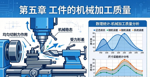
18, the system, under the action of uniform cutting force will appear force deformation, there are adjustment error, there are 2 variable value system error, error size and direction according to a certain law, such as machine tools, fixtures, tools in the thermal deformation of thermal equilibrium before the tool wear and other factors caused by the machining error, and machining error statistical classification, the fifth chapter on the quality of the workpiece machining, the existence of random error in the sequential processing of a batch of Workpiece, the size and direction of irregular changes in machining error, it should be noted that the random error from a single workpiece to see its changes irregularly, but from the whole batch of workpieces seem to be consistent with the statistical law, that is, the normal distribution, 41, Chapter 5, the quality of machining of workpieces, machining error has a statistical analysis method called the distribution curve method, will analyse the mathematical statistics in the analysis of the random error of the normal distribution curve method used for machining The analysis of error, 1, the method is through the measurement of the actual size of a batch of machined parts, to make the size distribution curve, the general situation, the actual distribution curve conforms to the normal distribution, and then according to the actual distribution curve.
19, the position of the line relative to the dimensional tolerance band, the shape, to carry out the analysis and calculation of the nature and magnitude of machining errors, 2 For a normal distribution curve, there are two characteristic parameters, the arithmetic mean of the measured dimensions, and the root mean square deviation of the random variable, 42 Chapter 5 Machining Quality of Workpieces, a 0 5 1 2 b have an effect on the normal distribution curve, where the arithmetic mean determines the position of the curve. standard deviation determines the shape of the curve, Conclusion, 43 Chapter 5 Machining Quality of Workpieces, Statistical Error Analysis Using the Distribution Curve Method, 44 Chapter 5 Machining Quality of Workpieces, The area of the curve distributed over a specific range, or probability, is 1, and the area of the curve distributed over a range z x, or probability A, can be determined by looking up Table 3 1, 45 In the machining process of a batch of parts, the machined dimensions of each part are measured individually and in sequence. During the machining of a batch of parts, the machined dimensions of each part are measured one by one and recorded sequentially in a data chart with the part number as the horizontal coordinate and the part dimensions as the vertical coordinate, Chapter 5 Machining Quality of Workpieces.
20, the amount of analysis, the above figure is on the lathe using the adjustment method of processing a number of parts journal obtained by the point map, due to the processing of tool wear is quite significant, resulting in the increase in the size of the diameter of the workpiece, showing an approximate flat-top distribution, the constant value of the systematic error is s, the variable value of the systematic error of the change in the slope of the tan, the distribution of the random error range of 6, the use of the point method, based on the actual size of the measured points, drawing point map to carry out the analysis of, 46 Machining error synthesis, chapter 5 the machining quality of the workpiece, solution, 1 for the actual distribution of dimensions and dimensional tolerance band diagram, 47 check table 3 1, there are A 0 9542, A 2 0 9542, 2 0 4771, the rate of non-conforming products Q 0 5, 0 4771, 2 29, the rate of conformity of P 1, 2 29, 97 71, 3 calculate the rate of conformity as well as the rate of rejects, chapter 5 the machining quality of the workpiece , 2 Analyse the nature of error and calculate the magnitude of error, 4 Improvement measures to improve the process.
21. The ability, like changing to a high-precision machine tool, to re-adjust the machine, to get the centre of the tolerance band as close as possible to the centre of the distribution, 48. Chapter 5: Machining Quality of Workpieces, Section III: Factors Affecting Surface Quality, I: Factors Affecting Surface Roughness, II: Influence of Tool Structure Parameters, III.Influencing factorsThere are tool tip arc radius r, main deflection angle r, vice deflection angle r, feed f, 49. chapter 5 the machining quality of the workpiece, the conclusion is that f decreases, r, r decreases, r increases, so that the value of the surface roughness decreases, the physical factors of the accumulation of chip tumour, the influence of scale spurs, the factor of the workpiece material, the formation of the accumulation of chip tumour with the plasticity of the workpiece material as well as the strength, hardness is related to the plasticity of the workpiece material and workpiece material plasticity, it is easy to form the accumulation of chip tumour,. Workpiece material strength, hardness, the height of the accumulated chip tumour is reduced, but when v is 2, 33m/s, the strength of various materials, the hardness of the impact of the difference is not great, so the processing of low carbon steel, can be carried out first normalising or tempering treatment, in order to reduce the material.
22, material plasticity 50, chapter 5 on the machining quality of the workpiece, cutting speed has an impact on it, the growth of chip tumour and cutting speed associated with the larger, in general, in the low and high speed cutting, not easy to form chip tumour, however, in the medium speed, that is, v for 10 to 50m/min range, easy to produce chip tumour and scale spurs, at this time the surface roughness is the worst. 51, chapter 5 on the machining quality of the workpiece, process system vibration has an impact,, process system vibration will make the tool relative to the workpiece to produce periodic displacement, the formation of similar ripple marks on the machined surface, reduce or eliminate the process system vibration. Chapter 5 on the machining quality of the workpiece, the process system vibration has an impact, the process system vibration will make the tool relative to the workpiece to produce periodic displacement, the formation of ripple-like traces on the machining surface, reduce or eliminate the process system vibration is to reduce the surface roughness of the effective measures, vibration has forced vibration and self-excited vibration of the two kinds of vibration, reduce or eliminate the vibration of the measures have to improve the process system stiffness, increase the system resistance, increase the system stiffness, increase the system resistance. The measures to reduce or eliminate vibration include increasing the stiffness of the process system, increasing system damping, correctly selecting the tool and cutting dosage, using vibration damping devices, using damping materials, adding damping materials to parts, friction dampers mounted on the tailstock of the lathe.52 Surface hardening, work-hardening, the concept of via.
23, for the surface after cutting, its hardness will often be one to two times higher than the base hardness, hardened layer depth can reach dozens of microns up to hundreds of microns, this is not caused by heat treatment of the surface hardening phenomenon, known as hardening of the processing, the factors affecting the surface strengthening, mainly in the cutting process of the metal occurred in the consequences of plastic deformation, the greater the plastic deformation, then the surface strengthening of the degree of the more powerful, on the other hand, because of the presence of cutting heat and will lead to surface weakening, generally at low temperatures, the second is the quality of machining workpiece. The greater the plastic deformation, then the surface strengthening of the more powerful, on the other hand, because of the existence of cutting heat, and will trigger the surface weakening, generally in the case of the temperature is not high, the surface strengthening occupies a dominant position, Chapter 5 is related to the quality of machining of the workpiece, and the second is the influence of the surface strengthening and the surface of the residual stress factors, 53 elaboration of the concept of residual stress, after the completion of the cutting process, the volume of the surface layer appears to change, resulting in the surface layer to produce expansion or contraction After cutting, the volume of the surface layer changes, resulting in expansion or contraction of the surface layer, but hindered by the substrate, and then the existence of residual stress on the surface, the main factors affecting the residual stress on the surface of the workpiece, is the plastic deformation of the workpiece material, cutting heat and other factors triggered by the volume of the surface of the workpiece changes in the situation.
24, the form of stress, the residual stress on the surface of the workpiece exists tensile stress and compressive stress in these two forms, when the surface has residual tensile stress, its fatigue strength will be significantly reduced, should be avoided as far as possible tensile stress, and the surface of the residual compressive stress is conducive to the enhancement of fatigue strength of the parts, chapter 5, the quality of machining of the workpiece, the fourth section of the surface quality of the machine parts of the use of the performance of the effect of the impact of the surface, the impact of the abrasive wear, surface Roughness value is associated with wear resistance however there are limits, 54 Surface roughness value is associated with fatigue resistance, surface compressive stress can improve fatigue resistance, proper hardening can also improve fatigue resistance, surface roughness value is associated with corrosion resistance, surface compressive stress is conducive to improving corrosion resistance, surface roughness value is associated with a good fit quality, it has an effect on fatigue resistance, it has an effect on corrosion resistance, it has an effect on the quality of the fit, texture form and direction, arc shape and pit shape are better, appropriate hardening can improve wear resistance, the conclusion is that reducing the surface roughness value can improve the use of parts, Chapter 5 Mechanical Processing of Workpieces.
25, on the lathe, for the quality of 55 classroom exercises p67 of the short set of workpiece bore for semi-finish boring processing, machining before the bore roundness error is 0.4mm, machining after the roundness error required to reach 0.01mm, known as the lathe spindle stiffness with Js, the tool holder stiffness J frame for 3000N/mm, tailstock stiffness J tail with Js, CFC for 2500, try to analyse and calculate in only consider the machine tool rigidity impact, a feed roundness accuracy can meet the requirements of the drawing, if not to meet the requirements, can be commonly used in what kind of process measures, Chapter 5, the quality of machining of the workpiece, the solution, 1 for the stiffness of the process system Js, so only consider the machine tool rigid, so machine tool rigid is equal to the process system is rigid, i.e., Jjc is equal to Js, when machining on the lathe, the rigidity of the machine tool will be with the change of the tool position and change, but generally take the The tool is located in the workpiece at the midpoint of the stiffness of the representative, that is, the textbook of the formula 3.5, 56, Chapter 5, Chapter 5, Machining quality of the workpiece, 2 to find the error reproduction coefficient, 3 to find the error of the workpiece w, Conclusion, a feed can not meet the requirements, can be reduced by decreasing the amount of feed f, so as to reduce the error reproduction coefficient, according to the formula 3.14, there are.


No comments