
Boring, with further processing of forged holes, cast holes and drilled holes, is able to increase the diameter of the hole, improve accuracy, reduce surface roughness, and also be able to make better corrections to the original hole axis of the existence of the skewed situation. Boring there is a rough boring, semi-fine boring and fine boring of these classifications.
Boring there is a general boring and deep hole boring these two types, general boring with the help of ordinary lathe can be achieved, the boring tool is fixed in the tailstock of the lathe, or fixed in the small tool holder, can be achieved. Deep hole boring that is the need for special deep hole drilling and boring machine, the boring tool is to be added to the boring culm, but also with a hydraulic pump station, relying on coolant to exclude the iron filings Oh.
Boring tool working part of the installation, which is extremely important, especially for the use of eccentric principle to carry out the work of adjustment, after the installation of boring tool, be sure to pay attention to look at the boring tool of the main cutting edge on the plane, it and the boring head of the feed direction is not in the same horizontal plane? Only installed in the same level, to ensure that several chip edge in the normal processing cutting angle.
其BoringPrecision is extremely high, fine boring dimensional accuracy can reach IT8 to IT7, can control the diameter of the hole in the accuracy within the range of 0.01MM. If it belongs to fine boring.machining accuracyTT7 to IT6 can be achieved, andsurface qualityGood. The surface finish roughness Ra value is in the range of 1.6 to 0.8 μm for a typical boring.
Influencing factors and machining optimisation measures for internal hole turning
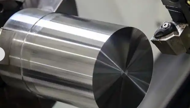
The operation of enlarging the bore of a workpiece or machining the inner surface of a hollow workpiece by means of turning is called bore turning, or boring, and can be performed by most external turning processes. In the case of external turning, the length of the workpiece and the size of the selected toolholder do not affect the tool overhang, and can therefore withstand the cutting forces generated during machining. In the development of boring and bore turning, hole depth determines the overhang, so that the hole diameter and length of the parts on the tool selection there is a great limitation, so it must be a combination of factors to optimize the machining programme.
The general rule for bore machining is:
1. Minimise tool overhang and select the largest possible tool size to achieve the highest machining accuracy and stability.
2, in view of the space constraints imposed by the diameter of the machined part hole, the choice of tool size will also encounter limitations in the machining, but also must take into account the chip removal and radial movement of the situation.
3, the purpose is to ensure that the inner hole processing with stability, during the processing operation, to select the correct hole turning tool, and it should be properly applied and reasonable clamping, so as to reduce the deformation of the tool, but also to minimise vibration, so as to ensure that the quality of the processing of the inner hole.
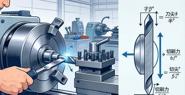
In bore turning, cutting force is a key factor that should not be ignored. For a given bore turning condition, such as workpiece shape, size, and clamping method, cutting force, regardless of its size or direction, is a key factor in suppressing vibration and improving machining quality in bore turning. When it comes to the tool's turn to start cutting, the tangential and radial cutting forces will cause the tool to deflect, which will gradually cause the tool to move away from the workpiece, causing the cutting force to deflect. When the tool is turning, the tangential cutting force and radial cutting force will cause the tool to deflect and gradually move the tool away from the workpiece, causing the cutting force to deflect, the tangential force will try to force down the tool, and will also make the tool move away from the centre line, resulting in the back angle of the tool becoming smaller, when the diameter of the hole turned is relatively small, it is necessary to maintain a sufficiently large back angle to prevent interference between the tool and the wall.
During the machining period, radial and tangential cutting forces cause the bore turning tool to deflect, which generally requires forced cutting edge compensation and tool vibration control. When radial deviation occurs, the depth of cut should be reduced to minimise chip thickness.
From the point of view of tool application:
1, the choice of blade groove type:
The cutting process is decisively influenced by the insert groove type. Positive front angle groove type inserts are usually used for internal hole machining, which have sharp cutting edge and high edge strength.
2. Selection of the main deflection angle of the tool:
Bore turning tool in the processing, the main deflection angle will have an impact on the radial force, axial force and the direction and size of the synthetic force, a larger main deflection angle will make the axial cutting force increase, smaller main deflection angle will lead to a larger radial cutting force, in general, the axial cutting force towards the direction of the toolpost usually does not have a large impact on the processing, so it is beneficial to choose a larger main deflection angle, in the selection of the main deflection angle, it is recommended to choose as close as possible to 90 ° and less than 75 ° main deflection angle. It is recommended to choose a main deflection angle as close as possible to 90° and not less than 75°, otherwise, it will cause a sharp increase in radial cutting force.
3, the selection of the tip radius:

A small tip radius should be the first choice when turning bores. If the tip radius is increased, the radial and tangential cutting forces are increased and the risk of vibration tendencies is increased. On the other hand, tool deflection in the radial direction is influenced by the relationship between the depth of cut and the tip radius.
When the depth of cut is less than the tip radius, the radial cutting forces will continue to increase as the depth of cut deepens, and when the depth of cut is equal to or greater than the tip radius, the radial deflection will be determined by the main deflection angle, and the rule of thumb for selecting the tip radius is that the tip radius should be slightly less than the depth of cut, so that the radial cutting forces are minimised, and, at the same time, when ensuring that the radial cutting forces are minimised, the maximum tip radius can be used to obtain a stronger cutting edge, better surface texture and more uniform pressure distribution on the cutting edge. At the same time, applying the maximum tip radius will result in a stronger cutting edge, better surface texture and more uniform pressure distribution on the cutting edge while ensuring that radial cutting forces are minimised.
4, the choice of edge treatment:
The cutting edge rounding (ER) of inserts has an impact on cutting forces. Generally speaking, the cutting edge rounding of uncoated inserts is smaller in size than that of coated inserts (GC), which should be taken into account, especially in the case of long tool overhangs and the machining of small holes. Wear on the back face of the insert (VB) can change the back angle of the tool in relation to the hole wall and can be a source of influence on the cutting action during machining.
5. Effective discharge of chips:
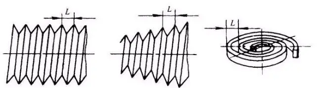
In the internal hole turning process, chip removal is also extremely important to the effect of processing and safety performance, especially when in the processing of deep holes and blind holes such as this situation is more so. The shorter spiral chip is the ideal chip for internal turning, this type of chip is relatively easy to be discharged, and in the chip breakage will not cause excessive pressure on the cutting edge.
Processing, when the chip is too short, chip breakage is too strong, which will consume more machine power, and there is a tendency to increase vibration, and once the chip is too long, it will make the chip discharge become more and more difficult, the centrifugal force will be pressed to the chip to the hole wall, the residual chip is squeezed to the surface of the processed workpiece, so there will be a risk of chip clogging and then damage to the tool. Therefore, the development of internal hole turning, recommended the use of tools with internal cooling, in this way, the cutting fluid will effectively discharge the chips out of the hole, the processing of through-hole, but also can replace the cutting fluid with compressed air, through the spindle to blow out the chips, in addition, the selection of suitable insert groove type and cutting parameters, but also on the control of the chip and discharge help.
6. Selection of tool clamping method:
The stability of the clamped tool, as well as the stability of the workpiece itself, is extremely critical for internal hole machining, given that it determines both the magnitude of the vibrations that occur during machining and whether or not such vibrations will increase. It is extremely important that the clamping unit of the toolholder meets the recommended length standard, as well as the surface roughness requirements and hardness conditions. The punctuation was added to maintain the original meaning, otherwise the last sentence would have been incomplete.
The clamping of the toolholder is a key stabilising element and during actual machining the toolholder will deflect. The deflection of the toolholder is determined by the material of the toolholder, the deflection of the toolholder is determined by the diameter of the toolholder, the deflection of the toolholder is determined by the overhang of the toolholder, the deflection of the toolholder is determined by the radial cutting forces, the deflection of the toolholder is determined by the tangential cutting forces and the deflection of the toolholder is determined by the clamping of the toolholder on the machine tool.
Even the slightest movement of the clamping end of the toolholder can cause the tool to deflect. High-performance toolholders should have a high degree of stability during clamping operations to ensure that there are no weak points in the machining process. To achieve this, the inner surface of the tool clamping must have a high surface finish and sufficient hardness.
For common toolholders, the highest stability can be achieved by using a clamping system that clamps the toolholder completely around the circumference. If the toolholder is supported as a unit, the performance is better than if the toolholder is clamped directly with screws. Screw clamping of the toolholder to the V-block is preferred, however, it is not recommended to use screws to clamp cylindrical shank toolholders, as screws acting directly on the toolholder can cause damage to the toolholder.
Boring process main problems
Tool wear
In the boring process, the tool is to maintain a continuous cutting state, in this case, it is easy to wear and tear and breakage and so on, which will make the hole processing dimensional accuracy is reduced, and then let the hole surface roughness value increased; at the same time, the calibration of the fine-tuning feed unit appeared in the abnormal situation, which led to the generation of the adjustment error, the adjustment error will lead to the processing of the hole diameter deviation, and in serious cases, even cause product quality failure. This adjustment error will cause the processing of the hole diameter deviation, and in serious cases, even cause product quality failure.
Changes in blade edge wear
processing error
After the boring process, its machining error will be reflected in the size of the hole after machining, will be reflected in the shape of the hole after machining, will also be reflected in the hole after machining surface quality changes, and the main influencing factors exist.
1. The length-to-diameter ratio of the cutter bar is too large or the overhang is too long;
2, blade material and workpiece material mismatch;
3, boring dosage is unreasonable;
4. Unreasonable allocation of residual adjustments;
5. The offset of the initial hole position leads to periodic changes in the residual quantity;
6, the workpiece material high rigidity or low plasticity, the tool or material is a tendency to let the knife;
surface quality
Boring, the surface that has been machined, the appearance of fish scale, or thread-like cut lines, which is a relatively common surface quality phenomenon.
Mainly due to mismatch between the feed and speed of the tool
Mainly due to rigid vibration of boring process and tool wear
Adjustment error
Boring process, because the operator to adjust the distribution of layer draft, in the process of adjusting the distribution of the feed allowance, if the operation is not appropriate, it is easy to trigger the machining of dimensional accuracy deviation.
measurement error
Inappropriate use of gauges during the post-processing measurement process and errors in measurement methods during boring operations are common quality hazards in boring operations.
1. Measuring tool failure
2. Incorrect measurement method


No comments