

01 Selecting the Angle of a Turning Tool
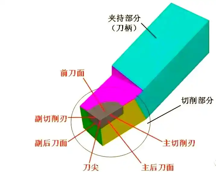
The structure of the cutting edge of a turning tool
The cutting section of a turning tool comprises several key components which collectively influence its geometric characteristics and cutting performance. These components include the rake face, the main rear face and the secondary rear face, as well as the main cutting edge, the secondary cutting edge and the tool tip.
The rake face is the surface on the cutting tool over which the chips flow; its shape and finish are crucial to the cutting performance.
Front cutting edge: This faces the machined surface of the workpiece and interacts with it; it is one of the key factors determining the cutting performance.
The rake face of the tool, which is opposite the machined surface on the workpiece and interacts with it, affects both the tool’s durability and the quality of the cut.
This is the main cutting edge at the junction of the front face and the rear face of the cutting tool; it is related to the main rear face, and its angle and sharpness have a direct impact on cutting efficiency.
The secondary cutting edge is located at the intersection of the tool’s front face and secondary rear face; together with the primary cutting edge, it forms the tool’s cutting edge.
The cutting edge tip is the point where the primary cutting edge meets the secondary cutting edge; its shape and position are of paramount importance for the stability of the cutting process. This cutting edge tip is often rounded or chamfered in order to optimise cutting performance.

Key Geometric Angles of Turning Tools and Their Selection
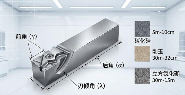
We must pay attention to the geometric angles of the turning tool; these angles include the rake angle, the clearance angle and the edge inclination angle, amongst others, and together they determine the cutting performance and service life of the turning tool.
1) Principles for selecting the forward angle (γ0)
When designing the rake angle, the aim is to strike a balance between the rigidity and sharpness of the cutting edge. When making a selection, the first consideration must be the hardness of the material being machined. For materials with a higher hardness, a smaller front angle should be selected; conversely, a larger front angle should be chosen for softer materials. In addition, the nature of the machining operation is also a key factor in determining the size of the front angle. During rough machining, a smaller front angle is appropriate to ensure the cutting edge has sufficient strength; however, during finish machining, a larger front angle should be selected to achieve higher cutting efficiency. Generally speaking, the front angle typically falls within the range of -5° to 25°.
Adjusting the rake angle ensures the cutting tool remains sharp and stable
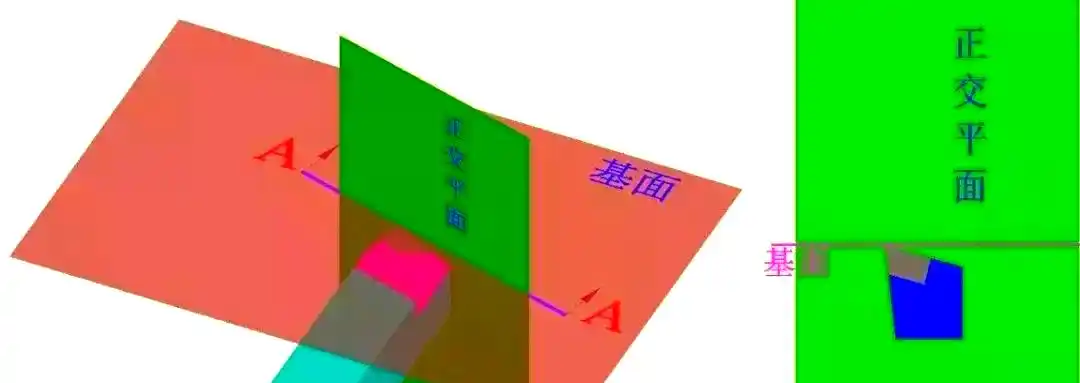
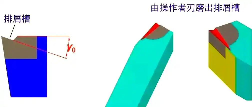
When manufacturing a turning tool, the rake angle (γ0) is not generally predetermined, but is instead achieved by grinding a chipbreaker groove onto the tool. This chipbreaker groove plays a crucial role. Not only does it effectively break up the chips, preventing them from becoming entangled, but it also controls the direction in which the chips are discharged, thereby ensuring the accuracy of the machined surface. At the same time, by reducing cutting resistance, the chip-breaking groove also extends the service life of the tool.
Principles for Selecting the Rear Angle (α0)
When selecting the rake angle, the first consideration should be the nature of the machining operation, followed by the hardness of the material being machined. During the finishing process, in order to achieve a superiormachining accuracyAs well as surface quality, a larger value is generally selected for the rake angle; however, during rough machining, given the need for higher cutting efficiency and tool durability, a smaller value is selected for the rake angle. For materials with a high degree of hardness, a smaller main rake angle is selected to enhance the rigidity of the cutting edge; whereas for materials with a lower degree of hardness, the choice of rake angle is relatively more flexible. It should be noted that the range of the rake angle is usually between 6° and 12°, and it must not be zero or a negative value.

Principles for selecting the principal azimuth (Kr)
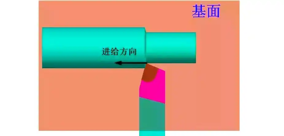
When selecting the principal rake angle, the first consideration must be the rigidity of the turning process system, comprising the lathe, the workholding fixture and the cutting tool. If this system is sufficiently rigid, then a smaller value for the principal rake angle is appropriate, which helps to extend the service life of the cutting tool, improves heat dissipation and optimises surface roughness. Secondly, the geometry of the workpiece is also a factor that must be taken into account when selecting the rake angle. For example, when machining a stepped feature, the rake angle should be set to 90°, whilst for workpieces requiring centre entry, a rake angle of 60° is typically selected. It is worth noting that the range of the principal rake angle generally lies between 30° and 90°, with 45°, 75° and 90° being the most commonly used angles.
Principles for selecting the secondary declination (Kr’)
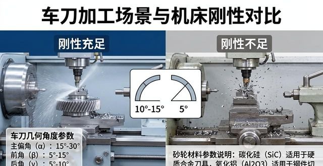
When selecting the secondary rake angle, the first considerations should be rigidity and machining characteristics, in order to ensure machining accuracy and stability. If rigidity is sufficient, it is advisable to select a smaller secondary rake angle to ensure machining accuracy and stability. Conversely, if rigidity is insufficient, a larger secondary rake angle should be selected to prevent vibration and damage during the machining process. Furthermore, the nature of the machining operation is also a key factor in determining the choice of secondary rake angle. For finish machining, it is generally recommended to select a secondary rake angle of between 10° and 15°; whereas for rough machining, the secondary rake angle can be set to approximately 5° to ensure sufficient cutting capacity and machining efficiency.
02 Grinding Wheels and Tool Regrinding
Grinding Wheel Materials and Applications
There are still some differences in regrinding strategies depending on the tool material. For example, the point angle of HSS drill bits is generally set at 118 degrees, and in certain special cases may even exceed 130 degrees; whilst their cutting edges are relatively sharp, the requirements for precision—such as edge height difference, symmetry and circumferential runout—are comparatively low. In addition, there are a wide variety of methods for regrinding cross-edges.
The point angle of an HM drill bit is typically set at 140 degrees; that of a straight-fluted drill is often 130 degrees; and that of a three-fluted drill is generally 150 degrees. The cutting edges of these tools, as well as the tips (i.e. the edges), are often not particularly sharp and may even be blunted; this is known as the ‘blunted edge’ and ‘blunted tip’ phenomena. However, the precision requirements for these tools are extremely high. To facilitate chip breaking, the cross-edge is usually ground into an S-shape.
The rake angle is of paramount importance to the performance of a cutting tool; if the rake angle is too large, it may lead to chipping of the cutting edge or cause the tool to “stick”, whilst if it is too small, it may increase frictional resistance, thereby affecting the cutting performance. The size of the rake angle is closely related to the hardness of the material being machined, the type of cutting tool and its diameter. Generally speaking, as the diameter of the cutting tool increases, the rake angle decreases accordingly; at the same time, the harder the material being machined, the smaller the rake angle required.
When selecting grinding wheels, different materials are suitable for grinding various types of cutting tools. For example, aluminium oxide grinding wheels are commonly used for grinding HSS cutting tools; they are reasonably priced and can be easily dressed into a variety of shapes, making them suitable for grinding complex cutting tools. Silicon carbide grinding wheels are primarily used for dressing CBN and diamond grinding wheels, CBN, or cubic boron nitride, grinding wheels are suitable for grinding HSS cutting tools; whilst they are relatively expensive, they offer high durability. Internationally, grinding wheel models are generally denoted by the letter ‘B’, such as B107, where the number represents the abrasive grain diameter. Diamond grinding wheels are used for grinding HM cutting tools; they are characterised by their high price and high durability. Their model numbers are denoted by the letter ‘D’ on the wheel, such as D64, where the number also represents the abrasive grain diameter.




 Chinese
  Japanese
  English
  German
  Finnish
暂无评论内容