

Explore | Technology | Practical Knowledge | Industry Exchange
In metal cutting operations, the cutting tool must penetrate the workpiece to carry out machining operations. The selection of the tool angle—which plays a crucial role in determining the geometry of the cutting edge—is of the utmost importance; it is exceptionally critical and vital, so crucial that it cannot be overstated, reaching a level of importance beyond imagination.
01 Selection of cutting tool angles
▍ Analysis of the cutting edge of a turning tool
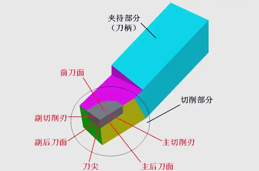
cooking oilcutting processThe core component of a turning tool is its cutting edge, which is precisely constructed from six distinct parts: the rake face, the main flank, the secondary flank, the primary cutting edge, the secondary cutting edge and the tool tip. The cutting performance and tool life are directly influenced by the shape and angles of each of these components. The cutting section of a turning tool comprises six key elements, and the interplay of their shapes and angles has a significant impact on cutting performance and tool life.
During machining, the surface of the cutting tool over which the chips flow is known as the rake face. Whether it is designed appropriately has a direct bearing on the smoothness of the cutting process and the quality of the finished workpiece. The main rake face is the surface of the tool that faces the surface of the workpiece being machined and interacts with it. It plays a crucial role in the stability of the cutting process and the quality of the machined surface, It exerts various influences, whilst the secondary rake face is situated opposite the machined surface of the workpiece and interacts with it; its design also affects the smooth and normal progression of the cutting process. Furthermore, the quality of the machined surface is also affected. The primary cutting edge is the line and area formed by the intersection of the tool’s rake face and the primary rear face; it is the primary component of the turning tool used for cutting. Its sharpness and angle directly influence cutting efficiency and machining quality. The secondary cutting edge is located at the intersection of the tool’s rake face and secondary flank. Together with the primary cutting edge, it forms the complete cutting section of the turning tool and plays a supporting role during the cutting process. The cutting edge tip is the point where the primary and secondary cutting edges meet; it is effectively a short curved or straight line, generally classified into two types: rounded tips and chamfered tips. The design of the cutting edge tip has a significant impact on the stability of the cutting process and machining accuracy.

▍ Reference plane for measuring the angle of the turning tool
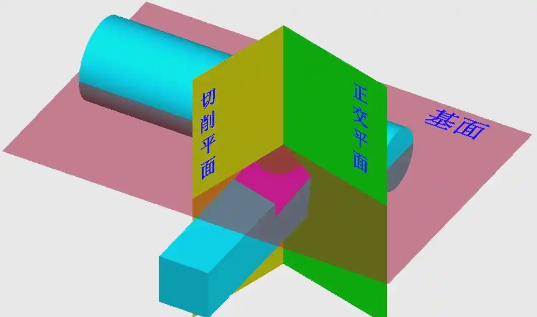
It is necessary to select appropriate auxiliary planes as reference surfaces in order to accurately measure the geometric angles of the turning tool. These three auxiliary planes are the cutting plane, the base plane and the orthogonal plane. They provide the necessary reference and basis for measuring the geometric angles of the turning tool.
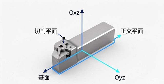
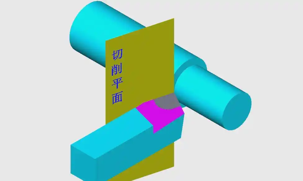
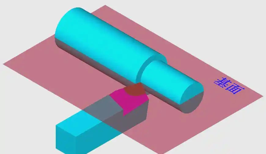
There is a plane known as the cutting plane; it is a plane that is tangent to a specific point on the main cutting edge and is also perpendicular to the base plane of the tool shank. It plays a crucial role in the measurement of turning tool geometric angles, providing the fundamental conditions for precise control of the cutting process; There is also a reference plane, which is a plane passing through a specific point on the main cutting edge and is parallel to the bottom face of the tool shank; During the measurement of turning tool geometric angles, the reference plane and the cutting plane work in conjunction to provide the fundamental support for the precise control of the cutting process; there is also an orthogonal plane, which is perpendicular to both the cutting plane and the reference plane at the same time. It plays a crucial role during the measurement of the turning tool’s geometric angles; together with the cutting plane and the reference plane, it lays a solid geometric foundation for the precise control of the cutting process. The cutting plane, the reference plane and the orthogonal plane—these three coordinate planes are mutually perpendicular and together form a three-dimensional Cartesian coordinate system.
▍ Selection of key geometric angles
Within a three-dimensional Cartesian coordinate system, we will examine in greater depth the key geometric angles of a turning tool and how to select them; these angles not only influence the cutting performance but are also directly linked to machining quality and tool life. Therefore, when selecting a turning tool, it is essential to consider the optimal combination of these angles comprehensively.
1) Principles for selecting the forward angle (γ0)
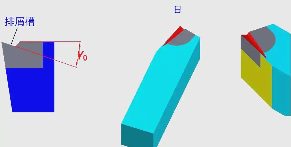
When selecting a turning tool, the size of the rake angle plays a crucial role, as it must strike a balance between the tool’s rigidity and sharpness. Specifically, the hardness of the workpiece material is the primary factor determining the rake angle. For high-hardness materials, a smaller rake angle should be selected, whilst for low-hardness materials, the rake angle may be increased appropriately. Furthermore, the nature of the machining operation is one of the factors influencing the choice of rake angle. During the roughing stage, a smaller rake angle is advisable to ensure the stability of the cutting edge; during the finishing stage, a larger rake angle should be selected to achieve higher cutting efficiency and machining quality. Generally speaking, the range for selecting the rake angle typically falls between -5° and 25°.
When manufacturing a turning tool, the rake angle (γ0) is not predetermined but is achieved by grinding a chipbreaker groove onto the tool. This chipbreaker groove plays a crucial role. Not only does it effectively break up the chips, preventing them from becoming entangled, but it also controls the direction in which the chips are ejected, ensuring the accuracy of the machined surface. Furthermore, it reduces cutting resistance, thereby extending the tool’s service life.
2) Principles for selecting the rear angle (α0)
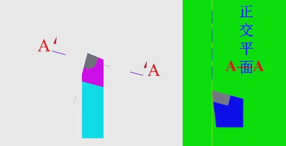
When performing machining operations, the selection of the rake angle is primarily influenced by two factors: the specific nature of the machining process and the hardness of the material being machined. During the finishing process of a workpiece, in order to ensure that the cutting tool maintains a high degree of sharpness and achieves precise machining accuracy, a relatively large rake angle must be selected; However, during the roughing stage, where greater cutting force is required, the rake angle should be set to a relatively smaller value. Furthermore, the hardness of the workpiece material itself also influences the final selection of the rake angle. If the material being machined is relatively hard, a smaller main rake angle should be selected to enhance the tool’s rigidity; conversely, a larger rake angle should be selected. It is important to note that the range of rear angles available is generally between 6 and 12 degrees, and it must never be zero or negative.
3) Principles for selecting the principal azimuth (Kr)
When selecting the main rake angle, the first consideration must be the rigidity of the turning process system, which comprises the lathe, the fixture and the cutting tool. Assuming the system rigidity is adequate, the rake angle should be set to a smaller value. This will help extend the service life of the cutting tool, optimise heat dissipation conditions, and improve the surface finish. Next, the geometry of the workpiece being machined is also a key factor determining the rake angle. For example, when machining a stepped feature, a rake angle of 90° is appropriate, whereas for workpieces requiring a centre-entry cut, a rake angle of 60° is generally selected. The range of values for the rake angle generally falls between 30° and 90°, with 45°, 75° and 90° being the most commonly used angles.
4) Principles for selecting the secondary declination (Kr’)
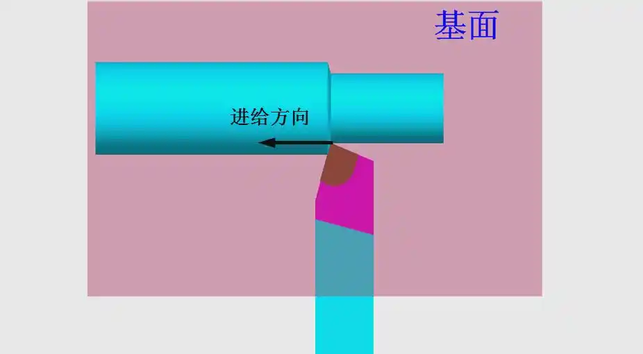
When selecting the secondary rake angle, the primary consideration is the overall rigidity of the turning tool, workpiece and fixture. Only when these components possess sufficient rigidity can a smaller secondary rake angle be selected to ensure machining accuracy and efficiency; conversely, if rigidity is insufficient, a larger secondary rake angle should be selected to ensure machining safety. Secondly, the nature of the machining operation is also a key factor in determining the secondary rake angle. During finishing operations, to achieve a higher surface finish, the secondary rake angle is generally set between 10° and 15°, whereas during roughing operations, to ensure cutting efficiency, the secondary rake angle may be set at around 5°.
5) Principles for selecting the rake angle (λS)
The choice of rake angle is primarily determined by the nature of the machining operation. During the roughing stage, given the significant impact forces exerted by the workpiece on the turning tool, it is recommended to select λS ≤ 0°; As for the start of the finishing stage, since the impact force exerted by the workpiece on the turning tool is relatively small, λS ≥ 0° may be selected; generally, a value of λS = 0° is adopted. The range of values for the rake angle is typically between -10° and 5°.






 Chinese
  Japanese
  English
  German
  Finnish
暂无评论内容