

Tools used in arc welding—such as the welding tongs and face shields used in manual metal arc welding, and the welding torches used in gas shielded arc welding—have already been discussed in specific chapters; this subsection will focus solely on welding fixtures and jigs.

Requirements for welding fixtures:
Welding jigs and fixtures should ensure that the dimensions and shape of the assembly are correct.
When installing welding fixtures, they should be lightweight, convenient and easy to operate; the same applies when dismantling them. The process must not hinder the welding operation in any way, nor should it obstruct the welder’s field of vision. This will improve the efficiency of assembling the workpieces and ensure that the entire process runs smoothly and efficiently.
Welding fixtures must provide highly reliable clamping and just the right degree of rigidity, ensuring that the workpiece does not become loose whilst avoiding excessive restraint, thereby reducing welding stresses and consequently preventingWelding distortion.
Welding jigs and fixtures should be simple in design, easy to manufacture, and safe and convenient to use and adjust.
Commonly Used Welding Fixtures and Jigs
During the welding process, the jigs used to position the workpieces in a specific orientation are known as positioners. Positioners are generally fairly simple in design and, depending on the product, are usually made in-house. They consist of stop blocks, positioning pins, V-blocks and similar components.
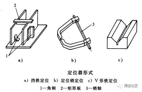
Angle sections, rectangular plates and similar components are arranged appropriately around the perimeter of the assembly or component to be welded, thereby positioning the workpiece relative to a horizontal or vertical plane, as illustrated by figures 1 and 2 in Figure a below. This is one of the simplest positioning methods; however, it does not offer a high degree of accuracy.
Positioning pins, which are used for positioning via machined holes in components, offer a high degree of precision, as illustrated by reference 3 in Figure b. Furthermore, these positioning pins not only serve to control the angle between the two profiles, but also ensure precision. V-blocks are commonly used for the clamping and positioning of cylindrical parts such as tubes, shafts and small cylindrical sections.
V-block positioning: V-blocks are frequently used to secure and position cylindrical parts such as pipes, shafts and small-diameter cylindrical sections, as illustrated in Figure c. The angle of the V-block’s groove is generally 90° or 120°.
During assembly, clamping tools are used to secure and hold the workpiece in place, preventing it from moving during the welding process. Common clamping tools, such as those shown below, are used to secure assembled components.
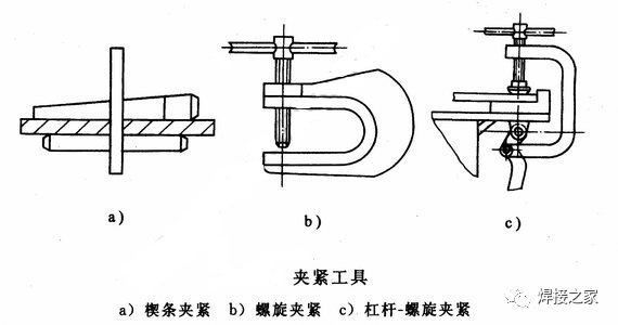
A typical application of a spiral clamp is shown in the figure below.
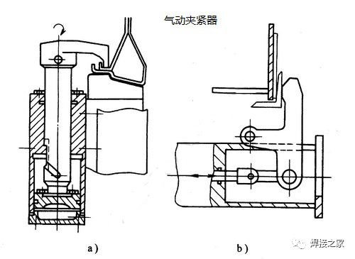
In the context of mass production or large-scale manufacturing, pneumatic and hydraulic clamps are widely used and come in a wide variety of forms; they not only clamp workpieces but can also be used to control and correct deformation in welded components. The images shown below illustrate the application of pneumatic clamps.
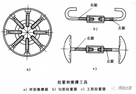
There is a type of clamping device known as a tensioning and bracing clamp, which comprises three types: jacks, tensioners and braces.
A jack is used to support the weight of the workpiece, and also serves as a support surface or to push and clamp the workpiece. Should beams and columns in large welded structures become deformed, jacks are often used to correct this.
Supporting devices are frequently used during the welding process to correct the shape of the workpiece, eliminate butt-joint misalignment and prevent distortion during welding. For example, to eliminate ovality, concavity and other similar defects in welded cylindrical sections and cylindrical products, a ring-shaped thrust support fitted with several radially arranged screw jacks (as shown in Figure a below) may be used; this is an effective method for correcting cylindrical walls with a thickness of 15 mm or less.
A device used during assembly to clamp two or more components in place is known as a clamp. The screw clamps used in production to secure welded parts are similar to those shown as ‘b’ and ‘c’ in the diagram above. A clamp consists of two push rods with left- and right-hand threads, respectively, and a connecting piece in between.
Flexible modular jigs
At present, flexible modular jigs can fully replace specialised jigs for product alignment and welding clamping operations; At the same time, it can be used in conjunction with simple, dedicated positioning devices to meet the alignment and clamping requirements for complex workpieces, thereby adapting to the positioning needs of different products and structures, and ultimately achieving the objectives of reducing jig investment costs and accelerating the product manufacturing process. Flexible modular jigs are primarily composed of the following structural modules:
(1) With regard to the base components, the worktable presents the following situation: of its five working surfaces, some feature a 100 mm × 100 mm grid—which generally belongs to the D28 series—whilst others feature a 50 mm × 50 mm grid, which generally belong to the D16 series. Furthermore, the worktable is marked with scale graduations; these graduations facilitate dimensional measurement during the assembly of workpieces, as well as the positioning measurement of locating seats, as illustrated in Figure 1. Furthermore, the worktable is available in two forms: cast and welded, allowing the appropriate type to be selected based on product weight, load-bearing requirements and other factors.
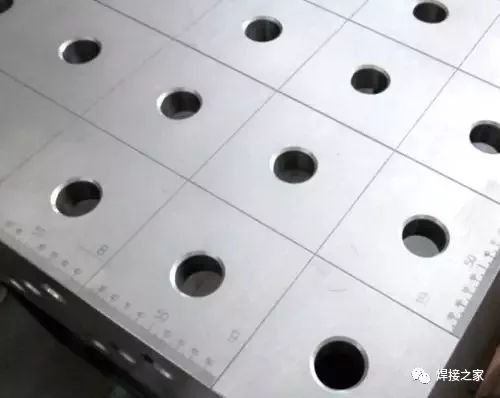
Figure 1: Workbench
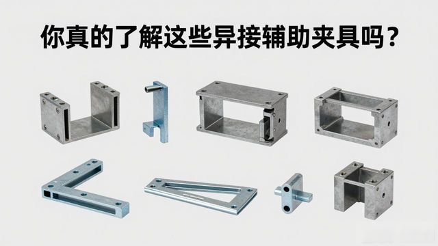
(2) Support components include U-shaped square boxes, L-shaped square boxes, angle irons, angle brackets and corner connectors, amongst others.
(3) Components used for positioning include positioning squares, positioning straight edges, flat squares and V-blocks; these are shown in Figure 2 and take the form illustrated there.
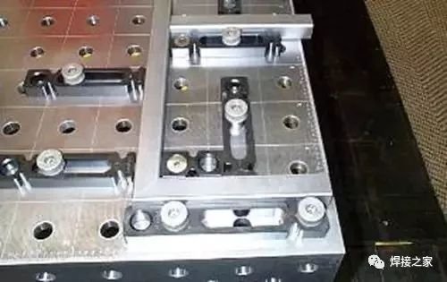
Figure 2: Positioning block
(4) There are various types of fasteners, including quick-release pins, countersunk locking pins and handle-operated quick-release fasteners, as shown in Figure 3.
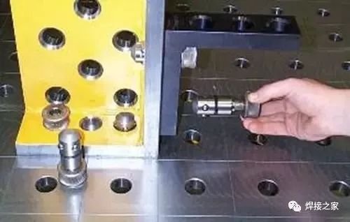
Figure 3: Locking pin
(5) Other accessories: tool trolleys, replacement parts, oilstones, brushes, etc.
Organisers
 Chinese
  Japanese
  English
  German
  Finnish
Leave a Reply
You must be logged in to post a comment.