
Abstract: In the machining process, machining accuracy is a core component of machining quality. Numerous factors often influence the final machining quality of a workpiece. This paper discusses several key factors affecting machining accuracy. Among the numerous sources of error, machine tool geometric errors, stress-induced deformation of the process system, and thermal deformation play a significant role. By understanding how these factors contribute to machining errors, it is possible to ensure that the workpiece meets the required quality standards.
1. Errors arising from the manufacturing process
During the machining process, machining errors arise due to the use of approximate machining methods, approximate transmission systems and approximate tool profiles.
1.1 Errors caused by the use of approximate machining motions
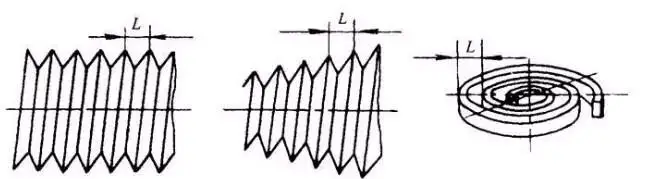
In many cases, in order to achieve the required workpiece surface finish, it is necessary to establish a specific relationship between the movements of the workpiece and the cutting tool. In theory, a perfectly precise and error-free relationship between these movements should be employed. However, applying a machining principle that is theoretically perfect can sometimes result in machine tools or fixtures becoming extremely complex, leading to manufacturing difficulties. Consequently, achieving high machining accuracy becomes difficult, and in some cases, it may even be impossible. For instance, when turning or grinding modular threads, where the pitch t = πm, the presence of the irrational factor π in the equation means that when deriving the pitch value through gear reduction, a fundamental error arises.
1.2 Errors caused by the use of an approximate tool contour
When machining complex surfaces using form-cutting tools, it is sometimes quite difficult to ensure that the tool edge perfectly matches the theoretical curve profile; consequently, simple approximations such as arcs and straight lines are often used to represent the theoretical curve. For example, when using a hobbing cutter to cut involute gears, due to the ease of manufacturing the cutter, an Archimedean basic worm or a normal-profile basic worm is frequently used in place of an involute basic worm, thereby introducing errors in the machining principle.
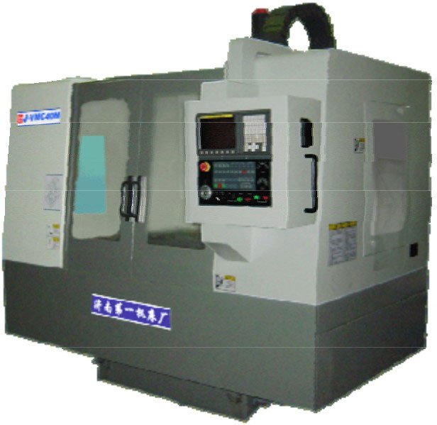
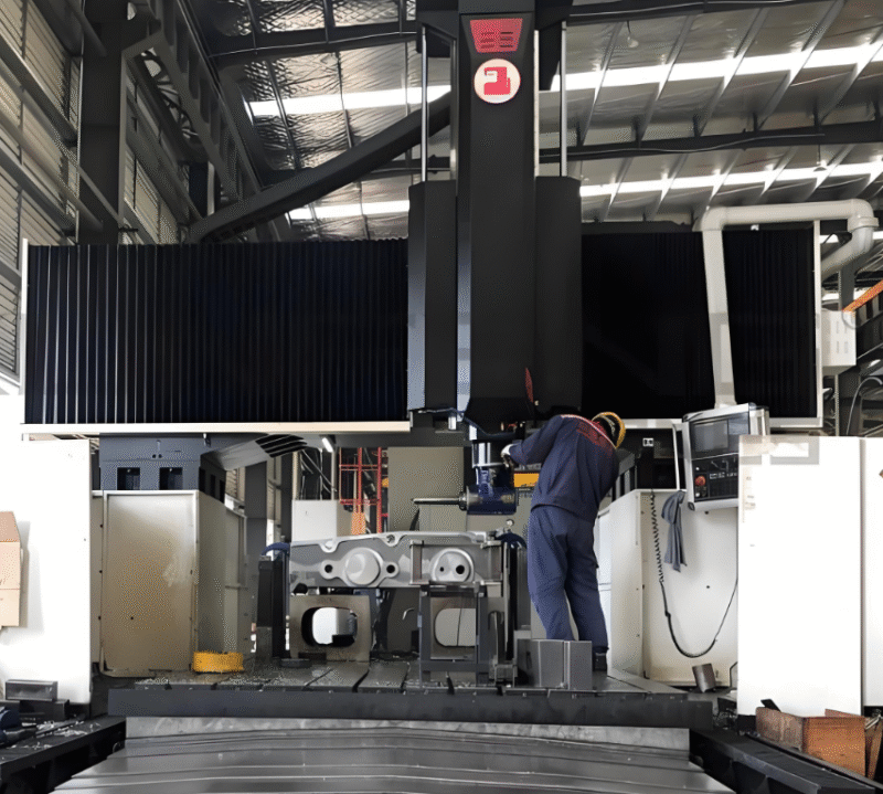
2 Geometric errors in machine tools
During machining, the relative motion between the cutting tool and the workpiece is usually achieved by means of the machine tool; consequently, the machining accuracy of the workpiece depends to a large extent on the accuracy of the machine tool. The manufacturing errors of the machine tool that have a significant impact on the machining accuracy of the workpiece include: spindle runout, guideway errors and errors in the transmission chain.
2.1 Spindle Rotational Error
Spindle rotational error refers to the deviation of the actual rotational axis of the spindle at any given moment from its average rotational axis. The primary causes of spindle radial runout include coaxiality errors between the various journal sections of the spindle, as well as various errors inherent to the bearings themselves. Other factors include coaxiality errors between the bearings and spindle deflection. Appropriately improving the manufacturing precision of the spindle and housing, selecting high-precision bearings, and enhancing the assembly precision of the spindle assembly can all contribute to improving the rotational accuracy of the machine tool spindle. Furthermore, balancing high-speed spindle assemblies and preloading rolling bearings are effective measures in this regard.
2.2 Guide rail errors
The guideways serve as the reference for determining the relative positions of the various machine tool components, and they also form the basis for the machine’s motion. In addition to manufacturing tolerances inherent to the guideways themselves, uneven wear and poor installation quality are significant factors contributing to errors in the guideways. Wear of the guideways is one of the primary causes of a decline in machine tool accuracy.
2.3 Drive Chain Error
In an internal transmission chain, the error in the relative motion between the drive and driven elements at either end is referred to as the transmission error of the chain. This error is caused by a combination of manufacturing and assembly errors in the individual components of the chain, as well as wear and tear during operation.
3 Manufacturing tolerances and wear of cutting tools and fixtures
As tool types vary, the impact of tool errors on machining accuracy also differs. Machining accuracy is influenced by tool errors; generally, for standard tools such as turning tools, boring tools and milling cutters, manufacturing errors do not have a direct impact on machining accuracy; whereas for dimension-specific tools such as drills, reamers, broaches and slot milling cutters, dimensional errors directly affect the dimensional accuracy of the workpiece; Furthermore, for form-cutting tools such as form cutters, form milling cutters and gear hobs, their errors primarily affect the geometric accuracy of the machined surface.Tool wearThis directly affects the positional relationship between the cutting tool and the workpiece surface, thereby causing dimensional errors in the workpiece. As jigs ensure that the workpiece is correctly positioned relative to the cutting tool and the machine tool, jig manufacturing errors have a significant impact on the machining accuracy of the workpiece (particularly positional accuracy). Fixture manufacturing errors consist of positioning errors, clamping errors, fixture mounting errors, guiding errors, indexing errors and fixture wear. Fixture wear can lead to positioning errors in the workpiece.
4 Positioning error
4.1 Reference non-coincidence error
There is a type of datum found on a part drawing that is used to determine the dimensions and position of a particular surface; this is known as a design datum. There is also another type of datum found on a process drawing, which is used to determine the dimensions and position of the machined surface following the current machining operation; this is known as a process datum. When machining a workpiece on a machine tool, it is necessary to select certain geometric features on the workpiece to serve as locating references for machining. If the selected locating references do not coincide with the design reference, a reference non-coincidence error will occur.
4.2 Errors arising from inaccuracies in the manufacture of the locating pair
The locating elements on a fixture cannot be manufactured with absolute precision to their nominal dimensions; their actual dimensions or positions are permitted to vary within separately specified tolerance limits. The locating surfaces of the workpiece and the locating elements of the fixture together form a locating pair. The maximum positional variation of the workpiece caused by the lack of precision in the manufacture of the locating pair, or by the clearance between the locating pair, is referred to as the locating pair manufacturing inaccuracy error.
5. Errors caused by thermal deformation of the process system
During machining operations, the process system undergoes a certain degree of thermal deformation under the influence of various heat sources. This is due to the uneven distribution of heat sources within the machining system, as well as differences in the structure and materials of its various components, which result in varying degrees of deformation across different parts of the system. Consequently, the precise positional and kinematic relationship between the cutting tool and the workpiece is compromised, leading to machining errors. Particularly in precision machining, machining errors caused by thermal deformation account for between 40% and 70% of the total machining error.
5.1 The Effect of Machine Tool Thermal Deformation on Machining Accuracy
Due to the influence of heat sources, temperatures in various parts of the machine tool will vary; owing to the uneven distribution of heat sources and the complex structure of the machine tool, various components of the machine tool will undergo thermal deformation to varying degrees. This disrupts the original relative positions of the machine’s components, thereby affecting machining accuracy. As different types of machine tools have different heat sources, the extent of this variation also differs in its impact on machining accuracy.
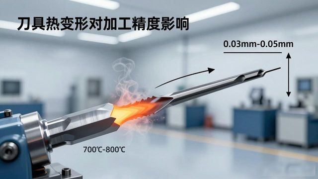
5.2 The effect of thermal deformation of cutting tools on machining accuracy

Although the heat transferred to the cutting tool during machining accounts for only 31% to 51% of the total heat generated, the tool’s small size and low thermal capacity mean that it still experiences a significant rise in temperature. This leads to thermal expansion of the tool, ultimately resulting in machining errors. During rough machining, the effect of tool thermal deformation on machining accuracy is negligible; however, for parts with high machining requirements, tool thermal deformation has a significant impact on machining accuracy, resulting in dimensional errors on the machined surface. For example, when turning with high-speed steel tools, the cutting edge temperature can reach 700°C to 800°C, and the thermal elongation of the tool can be as much as 0.03 mm to 0.05 mm.
5.3 The Effect of Workpiece Thermal Deformation on Machining Accuracy
Cutting generates heat, causing thermal deformation of the workpiece; the extent of this thermal deformation varies depending on the machining method and whether the heat is distributed evenly.
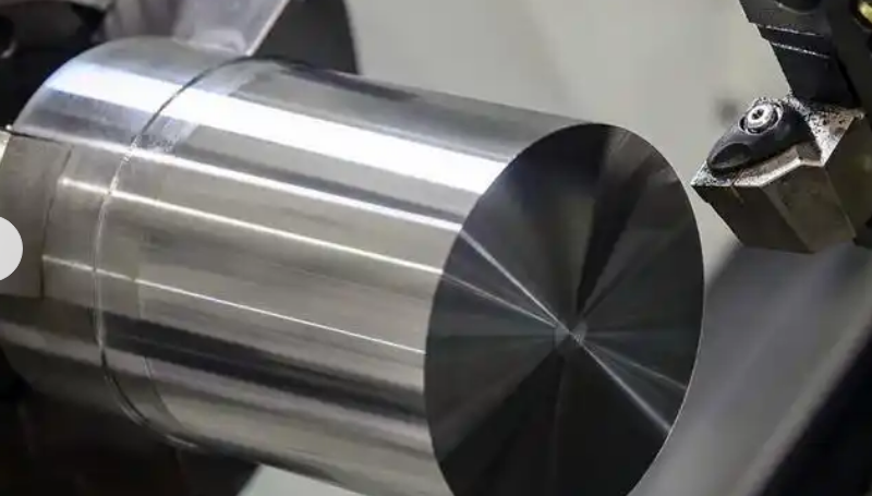
5.3.1 Uniform heating of the workpiece
For workpieces subjected to relatively uniform and consistent heating conditions—such as the outer cylindrical surfaces of shaft components during turning or grinding—both the length and diameter will contract to some extent after machining as the workpiece cools to room temperature, thereby resulting in dimensional errors; When machining disc-shaped or sleeve-type parts, particularly where the sleeve is short, the machining stroke is relatively short; consequently, it can be reasonably assumed that the temperature rise along the workpiece’s axial direction is uniform. When machining longer workpieces (such as long shafts), the workpiece temperature is low at the start of the feed operation, and the resulting deformation is relatively minor. As cutting progresses, the workpiece temperature gradually rises and its diameter increases progressively. Consequently, the thickness of the metal layer removed from the workpiece surface becomes greater. Upon cooling, this not only results in radial dimensional errors but also causes cylindricity errors; For workpieces with high requirements for axial accuracy (such as precision lead screws), axial elongation caused by thermal deformation will result in errors in the pitch.
5.3.2 Uneven heating of the workpiece
When a workpiece is heated unevenly—for example, when grinding a single surface of a part—the heat applied to only one side causes the workpiece to warp and bend. Once the workpiece has cooled after machining, this results in a concave profile error in the centre. This phenomenon is particularly pronounced when machining thin-walled parts.
6. Errors caused by stress-induced deformation in the process system
6.1 Basic Concepts
Machining systems undergo corresponding deformation under the action of cutting forces, clamping forces, inertial forces, gravitational forces and transmission forces. These deformations disrupt the correct relative position between the cutting tool and the workpiece, thereby reducing the machining accuracy of the workpiece.
6.2 Deformation due to insufficient workpiece rigidity under load
In a machining system, if the workpiece is less rigid than the machine tool, cutting tool or clamping fixture, the deformation caused by the workpiece’s lack of rigidity when cutting forces are applied will have a significant impact on machining accuracy.
6.3 Deformation due to insufficient tool rigidity under load
When a cylindrical turning tool is in use, its rigidity is at its highest along the direction perpendicular to the machined surface (the y-axis), meaning that any deformation it undergoes can be considered negligible. However, when boring small-diameter internal bores, the tool shank exhibits very poor rigidity; the deformation of the shank under load has a significant impact on the machining accuracy of the bore.
6.4 Deformation of machine tool components due to insufficient rigidity under load
Machine tool components are made up of multiple parts; to date, there is still no suitable, straightforward method for calculating their stiffness, and currently, experimental methods are still the primary means of determining the stiffness of machine tool components. Deformation and load do not exhibit a linear relationship; the loading curve and unloading curve do not coincide, with the unloading curve lagging behind the loading curve. The area enclosed between the two curves represents the energy dissipated during the loading and unloading cycles; this energy is expended as work done by friction. Only after repeated loading and unloading cycles does the starting point of the loading curve coincide with the end point of the unloading curve, and the residual deformation gradually decrease to zero.
6.5 Rigidity of the machining system and its effect on machining accuracy
6.5.1 Errors caused by changes in the stiffness of the process system
6.5.2 Errors caused by variations in cutting forces
During the machining process, variations in cutting forces—caused by factors such as changes in the workpiece’s machining allowance and non-uniform material composition—lead to changes in the deformation of the machining system, thereby giving rise to machining errors.
6.5.3 Errors caused by clamping deformation
During the clamping process, if the workpiece has low rigidity and the direction of the clamping force or the choice of clamping point is not appropriate, this may cause the workpiece to deform, thereby leading to corresponding machining errors.
6.5.4 The influence of other forces
6.6 Methods for minimising structural deformation in process systems
As discussed earlier regarding the rigidity of the machining system, it is clear that to reduce deformation of the system, one must increase its rigidity, thereby reducing cutting forces and minimising their fluctuations.
6.6.1 Improving the stiffness of the process system
6.6.2 Reduction of cutting forces and their variation
By carefully selecting the cutting tools, increasing the front angle and the main rake angle, and improving the machinability of the workpiece material through appropriate heat treatment, it is possible to reduce cutting forces.
7 Errors caused by residual stresses in the workpiece
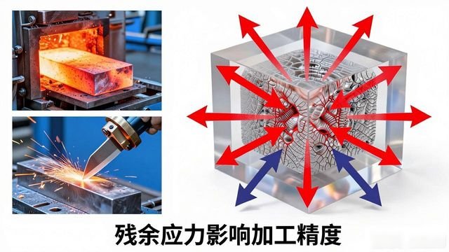
The stresses that remain within a workpiece after the external load has been removed are known as residual stresses. Residual stresses arise from uneven volume changes in the metal; The external factors responsible for the generation of residual stresses stem from both hot and cold working. Components with residual stresses are in an unstable state; once the equilibrium of their internal stresses is disrupted, the distribution of these stresses will change, thereby triggering new deformation and affecting machining accuracy.
7.1 Causes of internal stress
Internal stresses are primarily caused by the following factors: firstly, those generated during the manufacture of the blank; secondly, those generated during the cold straightening process; and thirdly, those generated during machining.
7.2 Measures to reduce or eliminate internal stresses
1. Employ appropriate heat treatment processes. 2. Allow sufficient time for the tool to deform. 3. Furthermore, the part’s design must be sound; it should be simple in structure and have uniform wall thickness.
8 Adjustment error
In every stage of the machining process, it is necessary to carry out some form of adjustment to the process system; however, as adjustments cannot be made with absolute precision, adjustment errors inevitably arise. Within the process system, the positional accuracy of the workpiece and cutting tool relative to the machine tool is ensured by adjusting the machine tool, cutting tool, fixture or workpiece. When the initial accuracy of the machine tool, cutting tool, fixture and workpiece blank all meet the process requirements, and dynamic factors are disregarded, the impact of adjustment errors plays a decisive role in machining accuracy.
9 Measurement errors
During machining, parts are subject to a variety of factors; furthermore, when measurements are taken after machining, factors such as the measurement method, the accuracy of the measuring instruments, the condition of the workpiece, and both objective and subjective factors can directly affect measurement accuracy.
10 Measures to Improve Machining Accuracy
10.1 Reducing systematic error
Improve the geometric accuracy of the machine tools used in part machining. Improve the accuracy of fixtures, gauges and the tools themselves. Control deformation of the machining system caused by external forces. Control thermal deformation of the machining system. Control tool wear. Control deformation caused by internal stresses. And control measurement errors. These all constitute direct reductions in primary errors. To improve machining accuracy, it is necessary to analyse the various source errors that give rise to machining errors. Depending on the specific circumstances, different corrective measures should be taken to address the primary source errors responsible for machining errors. When machining precision parts, one should maximise the geometric accuracy and rigidity of the precision machine tools employed, whilst controlling thermal deformation arising during the machining process; when machining parts with formed surfaces, the primary focus is on how to reduce the form errors of the forming tools and the mounting errors of the tools.
10.2 Error Compensation Method
For certain inherent errors in the process system, error compensation can be employed to control their impact on machining errors in the workpiece.
10.2.1 Error Compensation Method
This method involves artificially introducing a new initial error in order to compensate for, or offset, the inherent initial errors within the original process system, with the ultimate aim of reducing machining errors and improving machining accuracy.
10.2.2 Error Cancellation Method
By exploiting a pre-existing initial error, to partially or fully compensate for or offset that original error, or another type of pre-existing error.
10.3 Differentiating or homogenising the initial error
There is a method that can be used to improve the precision of a batch of machined parts; this method involves breaking down the initial errors. For the surfaces of parts that require a high degree of machining accuracy, there is another method, which involves gradually evening out the initial errors through a continuous process of trial machining.
10.3.1 Method of Decomposing the Initial Error (by Group)
In accordance with the laws governing error propagation, the dimensions of the blank or workpiece from the previous process are measured and divided into n groups based on size; the dimensional range of each group is thereby reduced to 1/n of the original. Subsequently, the precise position of the cutting tool relative to the workpiece is adjusted for each group based on its error range, thereby ensuring that the centres of the dimensional dispersion ranges for each group remain essentially consistent. Ultimately, this results in a significant reduction in the dimensional dispersion range of the entire batch of workpieces.
10.3.2 Averaging the original errors
This method involves a process whereby, through appropriate machining, the inherent errors in the surface being machined are continuously reduced and averaged out. What exactly is the principle behind homogenisation? It involves comparing and inspecting the surfaces of workpieces or tools that are closely related to one another, identifying the differences between them, and then carrying out corrective machining or reference machining in coordination with one another.
10.4 Carrying forward initial errors
The essence of the method described here is to shift the original error from a direction that is sensitive to error to one that is not, in other words, to transform the original error into a non-sensitive direction. The extent to which various types of inherent errors manifest as errors in part machining is directly related to whether these inherent errors lie in error-sensitive directions. If, during the machining process, measures are taken to encourage the transfer of these errors to directions insensitive to machining errors, machining accuracy can be significantly improved. In other words, the original errors are shifted to aspects that do not affect machining accuracy.
reach a verdict
In the machining process, errors are inevitable; only by conducting a detailed analysis of the causes of these errors can appropriate preventive measures be taken to reduce machining errors and improve machining accuracy. With the development of China’s machinery manufacturing sector and the growing demand for a wide variety of components, ever-greater precision in machining is inevitably required. Consequently, machining accuracy continues to play an irreplaceable role in the modern mechanical engineering field.


No comments