
When it comes to the custom machining of non-standard hardware components, CNC machining is a common method. What are the typical issues that can arise during this process? Today, the Mingte editorial team shares four common problems encountered in the CNC machining process; we will cover a further five in the next instalment.
1. The workpiece dimensions are accurate, but the surface finish is poor
This is because the cutting edge of the tool has become damaged and is no longer sharp; at the same time, the machine tool is experiencing resonance, is not positioned level, and is exhibiting crawling; furthermore, the machining process is substandard.
其prescriptionAs follows: If the cutting tool is worn or damaged and has lost its sharpness, it should be re-sharpened, or a better tool should be selected and the tool re-aligned; if the machine tool is vibrating or is not positioned level, it should be levelled and secured to ensure it is stable; The cause of machine crawling lies in severe wear of the saddle guideways, or wear or looseness of the ball screws. For the machine tool, attention should be paid to maintenance; metal shavings should be cleared after each shift, and lubricant should be applied promptly to reduce friction; Select a coolant suitable for the workpiece being machined; where other machining requirements allow, opt for a higher spindle speed wherever possible.

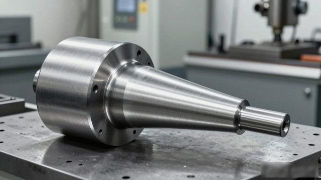
2. The workpiece exhibits tapered ends
The cause of the fault was that the machine tool had not been levelled properly during installation, resulting in one end being higher than the other and, consequently, an unstable mounting; During the turning of long shafts, the material used was relatively hard and the cutting depth of the tool was significant, which led to tool deflection; the tailstock centre was not aligned with the spindle.
Solution: Use a spirit level to adjust the machine tool’s levelness; lay a solid and reliable foundation; secure the machine tool firmly to enhance its rigidity; select appropriate machining processes and suitable cutting feed rates to prevent excessive stress on the cutting tool and subsequent tool deflection; and adjust the tailstock.
3. The drive phase indicator is working correctly, yet the dimensions of the machined workpieces vary in size
The fault is attributable to the machine tool’s saddle operating continuously at high speed for extended periods, resulting in wear to the lead screw and bearings. Furthermore, the repeatability of the tool holder has deteriorated following prolonged use. Furthermore, although the saddle returns accurately to the machining starting point every time, the dimensions of the workpiece still vary. This phenomenon is usually caused by the spindle; high-speed rotation of the spindle causes severe wear to the bearings, which in turn leads to variations in machining dimensions.
Solution: Place a dial gauge against the base of the tool holder. Then, use the system to create a fixed cycle programme to check the repeatability of the saddle. Afterwards, adjust the lead screw clearance and replace the bearings. use the dial gauge to check the tool holder’s repeatability, and subsequently adjust the machine or replace the tool holder; then use the dial gauge to verify whether the machined workpiece has accurately reached the programme’s starting point; if this is not the case, the spindle must be overhauled and the bearings replaced.
4. The workpiece dimensions differ from the actual dimensions by a few millimetres, or there is a significant variation in one axis
One cause of the fault is that the rapid positioning speed is too high, preventing the drive and motor from responding in time; another cause is that, following prolonged wear and tear, the mechanical slide, lead screw and bearings have become too tight and seized up; a further cause is that the tool holder is loose and cannot be secured properly after a tool change; Errors in the edited programme, such as the start and end points not corresponding, or the programme terminating without cancelling tool compensation, are also causes of failure; incorrect settings for the system’s electronic gear ratio or step angle are further causes of failure.
Solution: If the rapid traverse speed is too high, adjust the GO speed appropriately and fine-tune the acceleration, deceleration and timing of the cutting process, thereby ensuring that the drive and motor operate normally at their rated frequency; Should machine wear cause the saddle, lead screw and bearings to become excessively tight and seize up, readjustment and repair are essential; If the tool holder is too loose after tool change, check whether the tool holder’s reverse cycle time meets requirements, inspect the internal worm gear for wear, check for excessive clearance, and ensure it is not installed too loosely; If the issue is caused by the programme, the programme must be modified in accordance with the workpiece drawing specifications, appropriate machining processes selected, and an accurate programme written in strict accordance with the manual’s instructions; If excessive dimensional deviations are detected, check whether the system parameters are correctly set, particularly whether parameters such as the electronic gear ratio and step angle have been compromised; in such cases, measurements can be taken using a dial gauge.


No comments