

[Abstract] This paper addresses the inspection and rectification of issues—such as deformation—that frequently arise in the main girders of bridge (gantry) cranes during industrial production. It outlines several implementation methods, describes their respective characteristics, and explains their scope of application.
Keywords: main girder deformation, inspection, correction, methods
The detection and correction of main girder deformation are common issues encountered in industrial production. With regard to bridge (gantry) cranes, this article outlines several methods for detecting deformation, as well as several methods for correcting it, and explains the characteristics and scope of application of these methods.
I. Bridge (Gantry) CranesMain beam deflectionTesting
When carrying out safety and technical inspections of gantry (or portal) cranes, the measurement of the main girder’s camber is an extremely important aspect. Standard GB/T 82 (Technical Specifications for General-Purpose Bridge Cranes) explicitly stipulates that the upper camber of the main girder at the mid-span, F, is equal to L multiplied by (0.9 minus 1.4) and then divided by 1,000. Furthermore, the maximum camber shall be controlled within the range of L divided by 10 at the mid-span. Currently, the most commonly used method isDetection Methods, These include the traditional wire-pulling method, the current hook-suspension method, and the magnet-suspension method. These methods will be described in turn below.
1. The wire-pulling method
The steel wire method requires three inspectors, all of whom must be positioned on the crane’s main girder. A fine steel wire with a diameter of φ0.5 mm must be used, with one end of the wire secured to one end of the main girder and the other end connected to a 15 kg spring balance mounted at the opposite end of the main girder via levelling blocks on the top flange. Next, measurement points must be selected to measure the vertical distance from the wire to the upper surface of the main girder, after which the camber value is calculated. This method has significant limitations, as well as the risk involved for inspectors carrying out work at height. It is only used to inspect the camber of the main girder on certain box-girder double-girder bridge cranes; however, it cannot be used to inspect the camber of single-girder bridge (gantry) cranes or box-girder double-girder bridge cranes fitted with skirt plates.
2. The suspended plumb line method
The ‘hook-suspended ruler’ method involves suspending a 300 mm steel ruler upside down from a hook, starting the trolley (electric hoist) running along the I-beam track, and, with the aid of a levelling instrument set up on the ground, measure the elevation values at various points along the main girder in sequence, and then calculate the camber value. This measurement method is subject to significant error and may occasionally yield contradictory results. Factors affecting measurement accuracy include:
Differences in the radius of the trolley’s running wheels, shape deviations in the track surface, and instances where the trolley has only three legs will all be directly reflected in the elevation readings; this means that the measured elevation values are not accurate, and consequently, the calculated camber values will also be inaccurate.
3. The magnetic plumb line method
Take a fine steel wire with a diameter of 0.5 mm, secure one end to a magnet and the other end to a 0.5 kg weight, then attach a 300 mm steel ruler, which can be adjusted in position, to the steel wire, then use a specialised insulated rod to attach the magnet to the underside of the main girder’s bottom flange or the underside of the I-beam track; this constitutes the magnetic suspended ruler method. Three measurement points are then selected at both ends of the main girder and at its mid-span. The readings on the ruler suspended from the magnet are taken using a levelling instrument set up on the ground, and the camber value at the mid-span of the main girder is calculated accordingly. The formula is as follows:
The mid-span arch rise is located at the main girder and is equal to the mid-span elevation minus one-half; this one-half is the sum of the elevation at the higher end of the span and the elevation at the lower end of the span.
Secure the steel ruler face-up on the fine steel wire; if the measured result is positive, this indicates an upward camber, whilst a negative result indicates a downward deflection. This method can be used to measure the camber of main girders on various types of cranes; it is simple and convenient, yields accurate results, and saves both time and effort.
II. Deformation of the main girder of a bridge (gantry) craneMethods of correction
Under the combined effect of its own weight and the load, the main girder of a bridge (gantry) crane will experience elastic deflection, which increases the resistance to the movement of the load-carrying trolley. To address this situation and compensate for the deflection of the main girder, the design requires the main girder to be fabricated with a specific degree of camber. Consequently, ensuring that the specified camber value falls within an appropriate range—neither too large nor too small—has become a key consideration in the design and manufacture of crane main girders.
However, the main girder of a bridge (gantry) crane undergoes permanent deformation to varying degrees during manufacture, and similarly experiences permanent deformation to varying degrees during its service life. Even during the manufacture of the main girder, due to factors such as the arch camber allowance not being appropriately calculated, the effects of temperature, and errors arising from welding processes, once welding is complete, the resulting camber, warp, horizontal lateral deflection and web verticality—which essentially refer to the distortion of the main girder—may not necessarily all meet the relevant requirements; therefore, correction work is required at this stage; Furthermore, if the two main girders of a single bridge crane exhibit discrepancies at the same cross-sectional height, corrective action is also required; Furthermore, during the actual operation of a crane, insufficient rigidity of the main girder, combined with prolonged operation at full load or a particularly harsh working environment—among other factors—can lead to adverse effects, resulting in permanent deformation of the main girder. Once the camber and warp or camber values fall to a certain level, appropriate repair and straightening work must be carried out, in accordance with the provisions of Clause 1.4.10 of the National Standard GB/T 85, namely the Safety Regulations for Lifting Machinery: “For general bridge-type cranes, when the trolley is positioned at the mid-span and under rated load, if the deflection at the mid-span of the main girder below the horizontal line reaches one seven-hundredth of the span length, and if repair is not feasible, the crane shall be scrapped in accordance with the regulations.” Therefore, during the manufacture and operation of bridge (or gantry) cranes, the straightening of the main girder is not only an essential procedure but also a critically important task. The method chosen for straightening will directly affect the effectiveness of correcting the deformation of the crane’s main girder; it will also influence the cost of straightening, as well as the aesthetic quality of the main girder and the safe operation of the crane. Consequently, a reasonable and correct straightening method is crucial and must not be overlooked.
Under the current circumstances, the methods available for correcting deformation in the main girder include the “flame straightening method”, the “prestressing method”, the “repeated welding method”, the “cutting method” and the “local cutting and shim method”. The specific method to be employed must be determined on a case-by-case basis; there is no one-size-fits-all approach. Only by being thoroughly familiar with the characteristics, scope of application and key considerations of each method can one accurately and appropriately select a correction scheme, thereby achieving relatively satisfactory results.
1、Flame correction method
In the case of flame straightening, the principle involves applying localised heat to a metal structure, causing “plastic compression” in certain areas; once cooled, the resulting residual localised compressive stress achieves the desired straightening effect.

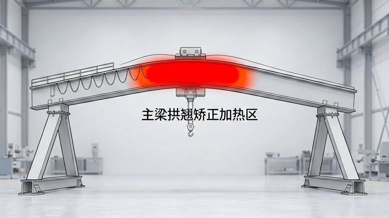
The heating zone for correcting the camber of the main girder is shown in Figure 1.
![图片[2]-桥(门)式起重机主梁挠度检测与变形矫正方法-大连富泓机械有限公司](/wp-content/uploads/2026/07/1783074570800_1.jpg)
Where the degree of arching is insufficient, focus on the triangular area beneath the heating plate and the rectangular area of the lower cover plate; where the degree of warping is insufficient, focus on the triangular area above the web of the heating cantilever and the rectangular area of the upper cover plate. The size, number and location of the baking points must be determined based on the specific circumstances of the deformation. However, the following points must be taken into account:
If the heating temperature is too low, it will certainly be unsuitable; if it exceeds 800 °C, it cannot be considered the best choice either; only the range between 700 and 800 °C is the most suitable. This is because, when heated to this temperature, the yield strength of low-carbon steel gradually approaches zero, causing the metal to enter a state known as “hot-work carbon steel”, which ultimately yields the most ideal straightening results.
The same area must not be heated repeatedly. Repeated heating will not only fail to produce the desired results, but will also cause damage to the metal’s microstructure.
(C) The heating points should be positioned at the web. This will reduce the waviness of the web.
Heating points must be kept clear of critical cross-sections; following heat straightening, the stress in the heated areas will increase, and consequently the load stress on the critical cross-sections will also increase, which could easily lead to deformation failure.
(E) Once the main beam has been straightened, it must be reinforced. This is because, following straightening, the stresses in the main beam are considerable. Furthermore, after many years of use, the metal material will gradually suffer from fatigue, resulting in a loss of rigidity. If reinforcement is not carried out, not only will the results of the straightening not be maintained, but the deformation will actually become more severe. Therefore, reinforcement is essential following straightening. Generally speaking, the reinforcement method involves using channel sections on both sides of the lower flange within the span of the main girder, and adding an extra layer of lower flange to the web to increase the cross-sectional area of the main girder.
The advantages of the flame correction method are:
The results achieved by the straightening process are quite satisfactory, particularly when applied to bent sections made of relatively hard materials, where it is equally effective.
•••• The construction process is also relatively straightforward.
Consequently, the flame correction method has been widely adopted. However, this correction method has the following shortcomings:
When carrying out flame straightening, in order to achieve a “compression moulding” effect, the section of the main girder being straightened must be raised so that the heating zone is subjected to compressive stress; otherwise, the process will be ineffective. This, in turn, increases the difficulty of the work.
Although the flame heating is concentrated at the partition, it can still cause a considerable degree of waviness in the web and top plate.
• Following flame straightening, the main girder must be reinforced; otherwise, more severe deformation will occur.
Based on the above discussion, under normal circumstances, we do not recommend the use of flame straightening, except for the correction of localised hard bends. However, for large-section steel, such as I-beams and channel sections, the flame straightening method is the most ideal approach when straightening or performing reverse deformation, as it does not require the use of large presses, nor does it require an excessively spacious workspace. Depending on the degree of bending in the structural steel, several heating points are selected accordingly—forming a triangular pattern on vertical surfaces and a rectangular pattern on horizontal surfaces. The size and number of heating points are determined by the extent of the deformation, enabling immediate correction in a manner that is both labour-saving and rapid.
2、Prestressing method
The principle behind the prestressing method for correcting the downward deflection of the main girder is as follows: using fixed supports at both ends of the deck slab beneath the main girder, multiple steel bars or steel wire ropes are tensioned by means of prestressing, thereby subjecting the main girder to a bending moment, Under the action of this bending moment, the upper half of the main girder is subjected to tensile stress, whilst the lower half is subjected to compressive stress. This bending moment causes the main girder to regain its upward camber, as shown in Figure 2. When the main girder is subjected to a load, the working stress is exactly opposite to the prestress in the reinforcing bars; consequently, the prestress in the reinforcing bars can offset part of the working tensile stress, thereby enhancing the load-bearing capacity of the main girder.
Figure 2
The prestressing method is an effective technique for correcting the deflection of main girders. It offers the following advantages:
Following correction, the camber value has become accurate and relatively stable; furthermore, it can be adjusted at any time in response to changes that arise during operation.
• Following correction, the strength and stiffness of the main girder are enhanced;
• The correction process is straightforward, easy to implement, quick and cost-effective.
However, it also has the following shortcomings:
• Applicable only to the correction of downward deflection in the camber of box-section main girders on bridge (gantry) cranes;
This method is not applicable to situations involving horizontal bending of the main girder, nor to cases of local deformation of the main girder, nor to the correction of cantilever deflection in gantry cranes.
• The appearance after correction is unattractive.
The prestressing method is most suitable when the crane has the following conditions:
• Cranes that have been in use for many years;
• The main beam lacks rigidity and has poor load-bearing capacity;
• The crane operates at full capacity for extended periods;
• Harsh working conditions, etc.
3. Repeated welding method
The principle behind the repeated welding method is to apply a high current to the main weld seam and use repeated welding to allow the resulting welding distortion to correct the original distortion, thereby achieving the objective of distortion correction. For example, when it is necessary to increase the camber of the main girder, repeated welding is carried out at the two fillet welds between the lower cover plate and the web of the main girder. As the weld cools and contracts, the resulting stresses will increase the upward camber. If it is necessary to reduce horizontal lateral deflection, repeated welding is carried out at the two fillet welds between the convex web and the upper and lower flanges, which will reduce the horizontal lateral deflection. The welding current and the length of the repeated welding must be determined according to the degree of correction required, taking care not to exceed the required correction, as this would necessitate subsequent corrective action in the opposite direction.
Many years of practical experience have confirmed that this correction method is the most effective, offering precision and efficiency, a smooth deformation process, and no cosmetic defects. This method is suitable for correcting arch camber, horizontal lateral deflection, and significant height differences between the two main girders of a bridge crane within the same cross-section, amongst other applications. It also offers numerous advantages, including practicality, cost-effectiveness, simplicity, high quality and speed. However, this method is not suitable for cases where a box girder exhibits a rigid bend at a specific point, nor for situations where the main girder has become insufficiently rigid and has undergone significant deformation following prolonged use.
4. Cutting method
Following the principle applied during the fabrication of earlier main girders—where the upward camber is formed by the contraction stress of the welds—welding deformation can be utilised to improve the camber of the main girder. However, in order to generate the required welding deformation, a relatively high welding current is usually required; this, however, may result in burn-through of the top flange or welding defects such as shrinkage cavities. Furthermore, it is difficult to control the magnitude and direction of deformation caused by welding thermal deformation, which can easily lead to other technical parameters of the main girder falling outside the specified tolerances.
Under certain circumstances, it is possible to utilise the effect of the main girder’s own weight on its arch-like camber to carry out cutting operations on the top plate of the main girder. Once cutting is complete, the modulus of resistance to bending of the main girder’s cross-section will be reduced at the cut location, thereby weakening the girder’s resistance to bending. Under the influence of the main girder’s own weight, it will undergo mechanical deformation, with the upward camber at the mid-span decreasing, whilst the upward camber at the cantilever ends increases. If this approach is adopted, it is relatively straightforward to control the entire correction process and the magnitude of the deformation. However, it should be noted that, with regard to the main and secondary web plates surrounding the cut, given that the main girder undergoes axial rotational deformation perpendicular to the web plates, there is a possibility of excessive wave-like distortion in the web plates, which must be prevented.
Practical experience has demonstrated that this approach is feasible, straightforward to implement and easy to control. Once the main girder has undergone permanent deformation, it is generally able to maintain its original technical specifications reasonably well; it does not undergo significant changes in technical parameters following the release of internal stresses or thermal deformation due to ageing. Consequently, the cutting method is an excellent technique for rectifying newly constructed main girders when their camber deviation exceeds the tolerance limits significantly. This method can also be used to correct excessive cantilever height (where the span meets specifications), excessive camber within the span (where the cantilever meets the standard), or other defects relating to upward camber or warping. The desired outcome can be achieved simply by selecting different support positions and cutting locations whilst the main girder is suspended. It should be noted that, where the correction required is substantial, it is essential to implement technical measures to prevent deformation of the web.
Apart from the four methods mentioned above, others—such as the local heating method—will not be discussed in detail here. In summary, the selection of various correction methods must be based on a comprehensive and careful analysis of the specific circumstances of the equipment requiring correction. This will enable a decision to be made as to which approach to adopt, or whether to combine several approaches, in order to achieve the best results in the shortest possible time and at the lowest possible cost.



 Chinese
  Japanese
  English
  German
  Finnish
No comments