
1. The field to which the utility model belongs is the technical field of bridge construction, specifically, there exists a steel girder assembling pre-arch degree adjustment device.
Background technology:
2. Accompanied by the accelerated development of the construction market, highway, high-speed rail and other engineering construction ushered in the development of a new peak, the application of steel-hybrid beams in high-speed rail and highway is increasingly common, these steel-hybrid beams have a large amount of work, complex technology, high cost and strict quality requirements, the steel-hybrid beams in the current construction market, the assembly site requirements of steel-hybrid beams, the use of the general assembly process is inefficient, poor accuracy, high labour consumption can not meet the needs of market competition. In the current construction market, the assembling site of steel-concrete beams has high requirements.
Technology Enabling Elements:
3. A steel girder assembling pre-arch degree adjustment device, which is involved in the technical problem to be solved by this utility model, is used with small terrain limitations, it is easy to operate, and it is detachable, which greatly improves the construction efficiency of steel girder assembling.
4. The utility modelTechnical programmeFor:
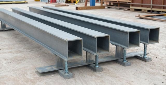
5. The steel beam assembling pre-arch degree adjustment device has a base, two height adjusting screws, which are threaded on the base, a support plate, the support plate is fixedly connected to the top of the two height adjusting screws, a row of up and down through the perforations are set on the base, and on the top of the base, at the periphery of each perforation, there is a corresponding connecting nut, and the two height adjusting screws are threaded into any two perforations and connected with the corresponding connecting nut. The two height adjusting screws are threaded into any two of the perforations and are threadedly connected with the corresponding connecting nuts.
There is a row of positioning steel tubes each from top to bottom passing through the mounting holes corresponding to those on the upper horizontal plate and the lower water plate, and the top of each positioning steel tube is fixed with the corresponding mounting holes on the upper horizontal plate, and the bottom of each positioning steel tube is fixed with the corresponding mounting holes on the lower water plate, and there are corresponding connecting nuts supported on the upper end of the upper horizontal plate and at the outer periphery of each mounting hole, and there are two height-adjusting screws penetrating into the inner holes of any two of the positioning steel tubes respectively. Two height adjusting screws are threaded into the inner holes of any two positioning steel tubes and connected with the corresponding connecting nuts.
7. A support plate comprising a support steel plate welded to the top of the two height adjusting screws, and a rubber pad fixed to the upper face of the support steel plate.
8. said two height adjusting screws are fixedly connected to the two end portions of the support plate respectively.
9. Said row of locating steel tubes has an equal distance between any two adjacent locating steel tubes.
10. Advantages of the utility model:

11. When steel beams are assembled, multiple steel beam assembly pre-arch adjustment devices are arranged and supported on the ground to support the bottom of the longitudinal beams to be assembled, which has a simple structure and is used with little terrain restriction; the height of the support plate of the utility model can be adjusted to achieve the adjustment of the pre-arch of the steel beams and the cross-slope, and the adjustment is made with the help of height adjusting bolts, which is simple to operate; two height adjusting bolts and the base are threaded and can adjust the position of the two height adjusting bolts on the base according to the different sizes of the support plate, and the dismantling is convenient and widely applicable. The two height adjusting bolts in this utility model are threaded with the base, and the position of the two height adjusting bolts on the base can be adjusted according to the different sizes of the support plate, which is convenient for dismantling and has a wide range of application.
illustrate
12.Figure 1 is the main view of the utility model.
13.Figure 2 is a side view of the utility model.
14.FIG. 3 is a schematic diagram of the structure of the utility model in the working state.
practical way of doing sth.
15. Next, the technical solutions in the embodiments of the utility model will be clearly and completely described in conjunction with the accompanying drawings in the embodiments of the utility model, and it is obvious that the embodiments mentioned are only a part of the embodiments of the utility model, but not all of the embodiments. Based on the embodiments of the utility model, all other embodiments obtained by the ordinary technical personnel in the field without making creative labour under the premise, all belong to the scope of protection of the utility model.
16.Seeing Fig. 1 as well as Fig. 2, there is a device named steel girder assembly pre-arch adjustment device, which comprises a base 1 and, in addition to that, there are two height adjusting screws 2, which are threadedly attached to the top of the base 1. In addition, there is a support plate which is fixedly connected to the top of the two height adjusting crossbars 2.
17. The base is a 1.2m double-pieced h-channel steel, which has an upper horizontal plate 11 with a row of mounting holes and a lower water plate 12 with the same row of mounting holes, and the mounting holes in the centre-axis position of the two correspond to each other up and down one by one, and the two vertical plates 13 connecting the upper horizontal plate 11 and the lower water plate 12, and a row of locating steel tubes 3, which is a steel pipe with an outer diameter of 60mm and a wall thickness of 3.2mm, passes through the upper horizontal plate 11 and the corresponding mounting holes of the lower water plate 12 from the top to the bottom respectively. A row of positioning steel tubes 3, 60mm OD, 3.2mm wall thickness steel tubes, pass from top to bottom through the mounting holes corresponding to the upper plate 11 and the lower plate 12 respectively, the top end of each positioning steel tube 3 is fixedly connected to the mounting holes corresponding to the upper plate 11, and the bottom end is also fixedly connected to the mounting holes corresponding to the lower plate 12, and the spacing of any two neighbouring positioning steel tubes 3 in the row is 20mm, and the periphery of each mounting hole on the upper face of the upper plate 11 is supported by the corresponding connecting nut 4, two 60cm length height adjusting nuts, and two 60cm length height adjusting nuts. In the upper horizontal plate 11, each mounting hole is supported by a corresponding connecting nut 4 on the periphery of the upper end face of the upper horizontal plate 11, and two height adjusting screws 2 with a length of 60cm are threaded into the inner holes of any two positioning steel tubes 3 and connected to the corresponding m48 nuts of the connecting nut 4, and the supporting plate consists of a supporting steel plate 5 with a thickness of 30mm welded on the tip of the two height adjusting screws 2, and a rubber pad 6 with a thickness of 5mm fixed on the upper end face of the supporting plate 5. The two height adjusting screws 2 are fixedly connected to the two ends of the support steel plate 5.
18. See figure 1
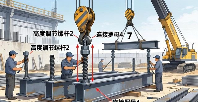
First, in FIG. 3, a plurality of steel girder assembling pre-arch adjusting devices are placed at a predetermined position with the aid of a planar position measurement, and then the height of the top surface elevation of the steel girder assembling pre-arch adjusting devices is adjusted by turning the connecting nut 4 of each of the steel girder assembling pre-arch adjusting devices to adjust the height of the top end of the height adjusting screw 2 which serves as a support plate. Afterwards, a gantry crane is used to transport the steel main beam 7 to a number of steel beam assembly pre-arch adjusting devices to carry out pre-assembly, and then temporary splicing plates, temporary bolts, and punching nails are used to temporarily fix the steel main beam 7, and when the whole span of steel beams has been temporarily assembled, the top elevation of the whole span of steel beams is measured, and the height of the top end of the height-adjusting screw 2 of the pre-arch adjusting device of the steel beam assembly pre-arch adjusting device is adjusted to make the pre-arch and the cross slope of the whole span of steel beams meet the requirements. Finally, use the high strength bolts to replace the temporary bolts and punching nails to achieve the assembly of the whole span of steel girders.
19. Even though examples of the present utility model have been shown and described, a person of ordinary skill in the art will understand that a variety of changes, modifications, substitutions, and variations can be made to the examples without departing from the principle and spirit of the present utility model, and that the scope of the present utility model is limited by the appended claims and their equivalents.
Technical characteristics:
1. The steel beam assembling pre-arch degree adjustment device is characterised in that it includes a base, two height adjusting screws which are threaded on the base, and a support plate which is fixedly connected to the top of the two height adjusting screws. The base is provided with a row of up and down through the perforations, the top of the base, in the periphery of each perforation are supported by the corresponding connecting nut, the two height adjusting screws were threaded into any two perforations, and with the corresponding connecting nut threaded connection. 2. There is a steel beam assembly pre-arch adjustment device, which is based on the description of claim 1, the base is a double-spliced h-channel steel, the base has an upper horizontal plate, and lower water The base has an upper horizontal plate and a lower water plate, and there are two vertical plates connected between the upper horizontal plate and the lower water plate, a row of mounting holes is provided at the centre axis position of the upper horizontal plate, and the same row of mounting holes is provided at the centre axis position of the lower water plate, and the mounting holes on the upper horizontal plate and the lower water plate are one-to-one correspondingly up and down, and there is a row of locating steel tubes, which respectively pass through the corresponding mounting holes on the upper horizontal plate and the lower water plate from the top down, and the top of each locating steel tube is connected to the corresponding mounting holes on the upper horizontal plate and the lower water plate. The top end of each positioning steel pipe is fixedly connected to the corresponding mounting holes on the upper horizontal plate, and the bottom end of each positioning steel pipe is fixedly connected to the corresponding mounting holes on the lower water flat plate, and at the upper end surface of the upper horizontal plate, and at the outer periphery of each mounting hole, there are supported and provided with corresponding connecting nuts, and there are two height-adjusting screws, which are respectively penetrated into the inner holes of any two positioning steel pipes, and at the same time threadedly connected with the corresponding connecting nuts. 3. The steel girder assembling pre-arch adjustment device of claim 1, characterised in that the support plate comprises a support steel plate welded to the top of the two height adjusting screws, and a rubber pad fixed to the upper end surface of the support steel plate.4 The steel girder assembling pre-arch adjustment device of claim 1, characterised in that the two height adjusting screws are fixedly connected to both ends of the support plate.5 The steel girder assembling pre-arch adjustment device of claim 2, characterised in that the two height adjusting screws are fixedly connected to the two ends of the support plate. The steel girder assembly pre-arch adjustment device of claim 2, characterised in that the distance between two adjacent positioning steel pipes in the row of positioning steel pipes is the same.
Technical summary
There is a steel beam assembling pre-arch degree adjustment device disclosed by this utility model, which contains a base, two height adjustment screws threaded on the base, and a support plate fixedly connected to the top of the two height adjustment screws, the base is provided with a row of up and down through the perforations, and the top of the base and in the periphery of each perforation are supported by the corresponding connecting nut, and the two height adjustment screws are respectively threaded into any two perforations and connected with the corresponding connecting nut. Two height adjusting screws are threaded into any two perforations and connected with the corresponding connecting nuts. This device has small terrain limitations when in use, is convenient to operate and can be disassembled, and greatly improves the construction efficiency of steel girder assembling, and greatly improves the construction efficiency of steel girder assembling. It greatly improves the construction efficiency of steel girder assembling.
The technical researchers and developers are, respectively, Huang Weibing, Cheng Xinying, Zhao Yongqiang, Lin Feng, Xiao Linyong, Zhao Xiaoming, Cao Shaohua, Mu Zhaoxin.
Protected technology user: China Railway Fourth Bureau Group Fifth Engineering Co.
Technical Development Day: 2021.08.03
Technical publication date: 2021/12/24


No comments