
Hello, everyone.
We will explore many examples of programming together, next, to help you can easily master those techniques of manual programming of CNC cars.
![图片[1]-众多编程实例,助你轻松搞定数控车手工编程!-大连富泓机械有限公司](/wp-content/uploads/2026/04/1776774100728_0.png)
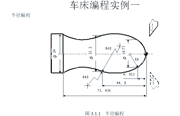
3110 (main procedure programme name)
N1 G92 X16 Z1 (Setting the coordinate system and determining the position of the tool setting point)
N2, G37, G00, Z0, M03, this operation is to move to the start of the subroutine and to allow the spindle to make a positive rotation.
N3 M98 P0003 L6 (call subroutine, repeat 6 times)
N4 G00 X16 Z1 (return to tool setting point)
N5 G36 (cancellation of radius programming mode)
N6 M05 (spindle rotation stopped)
N7 M30 (Main programme execution completed and reset)
0003 (subroutine name)
N1, G01 instruction is given, U-12 parameters are set, F100 speed is specified, and the tool performs a feed action to the cutting start position and leaves a subsequent cutting allowance.
N2, G03, U7.385, W-4.923, R8, for machining of arc segments with R8 radius.
A section of arc is machined with radius R60 and its radius is 60 at location N3 U3.215 W - 39.877 , an arc of radius R60!
By means of the N4 instruction, the G02 code is executed so that the U-axis is moved by 1.4 and the W-axis is moved in the opposite direction by 28.636 in order to machine an arc segment with a radius of 40, keeping an eye on the direction of the tangent line.
N5 G00 U4 (retreat from machined surfaces)
N6 W73.436 (return to cycle start Z-axis position)
Change the depth of cut at each cycle, N7, G01, U minus 4.8, F100.
N8 M99 (end of subroutine, return to main programme)
![图片[2]-众多编程实例,助你轻松搞定数控车手工编程!-大连富泓机械有限公司](/wp-content/uploads/2026/04/1776774100728_1.png)
3305
N1, G92, X100, Z10, this is to set the coordinate system, the purpose is to determine the position of the tool setting point.
Move the X-axis in the machine's co-ordinate system to a value of 16 and move the Z-axis to a value of 2 mm, after which the spindle is activated, this operation is done in order to move the machine to the starting point of the chamfer extension.
N3, G01 instruction with U value of 10, W value of minus 5, and F value of 300, (performs chamfering operation at an angle of 3 times 45 degrees).
N4 Z-48 (Machining Φ26 external circle)
N5 U34 W-10 (cutting the first tapered section)
N6 U20 Z-73 (cutting the second conical section)
N7 X90 (tool retracts to safe position)
N8 G00 X100 Z10 (Return to tool setting point position)
N9 M05 (Spindle rotation stopped)
N10 M30 (Main programme execution completed and reset)
![图片[3]-众多编程实例,助你轻松搞定数控车手工编程!-大连富泓机械有限公司](/wp-content/uploads/2026/04/1776774100728_2.png)
![图片[4]-众多编程实例,助你轻松搞定数控车手工编程!-大连富泓机械有限公司](/wp-content/uploads/2026/04/1776774100728_3.png)
3310
N10, G92, X70, Z10, this sets the coordinate system, the purpose of which is to specify the position of the tool setting point.
N20, the G00 instruction is executed, the U-axis moves negatively by 70 distances and the W-axis moves negatively by 10 distances, with the final aim of moving from the preset starting point to the centre of the front face of the workpiece.
That instruction with the word N30, a code like G01, a parameter like U26, a parameter like C3, and a speed value like F100 are used to perform a 3-by-45-degree right-angle chamfering operation.
N40 W-22 R3 (rounded R3)
The CNC machining code is N50, where the U value is 39, the W value is negative 14, and the C value is 3. It is used for machining a section where the length of an isosceles right-angled side is 3 like that.
N60 W-34 (Processing Φ65 external round)
N70 G00 U5 W80 (return to programming planning starting point)
N80 M30 (spindle stop, end of main programme and reset)
![图片[5]-众多编程实例,助你轻松搞定数控车手工编程!-大连富泓机械有限公司](/wp-content/uploads/2026/04/1776774100728_4.png)
![图片[6]-众多编程实例,助你轻松搞定数控车手工编程!-大连富泓机械有限公司](/wp-content/uploads/2026/04/1776774100728_5.png)
3312
The N1 code is used to set the coordinate system by applying the G92 instruction to set the X coordinate to 50 and the Z coordinate to 120, thereby clarifying the position of the tool setting point.
N2, M03, S300, in this state the spindle is shown rotating at 300 revolutions per minute.
Move directly to the starting position of the thread, where the speed increase stage is 1.5 mm and the depth of cut is 0.8 mm; move in a rapid manner to the horizontal coordinate number 29.2 and the vertical coordinate number 101.5.
Take N4, the instruction G32, the specific position Z19, F1.5 represents the feed speed, the thread is cut towards the end, and the range of the reduced speed section refers to the length corresponding to 1mm, which is the case.
N5 G00 X40 (X-axis fast backward)
N6 Z101.5 (Z-axis fast backward to thread start)
N7, the X-axis travels rapidly towards the front to reach the position of the start of the thread with a deep cut of 0.6 mm.
N8 G32 Z19 F1.5 (thread cutting again to the end)
N9 G00 X40 (X-axis fast back again)
N10 Z101.5 (Z-axis backs up again quickly to the start of the thread)
N11, X28.2, which means that the X-axis has to travel fast towards the start of the thread, while the depth of cut is 0.4 mm period.
N12 G32 Z19 F1.5 (third thread cutting to end)
N13 G00 X40 (Third fast reverse in X-axis)
N14 Z101.5 (Z-axis third rapid back-off to thread start)
N15, U - 11.96, the X-axis travels fast towards the start of the thread and the depth of cut is 0.16 mm.
Numbered N16, the G32 instruction is executed to move 82.5 units in the negative direction along the W axis at a cutting speed of 1.5 revolutions per minute, and this operation is the thread cutting to a new end operation.
N17 G00 X40 (X-axis fast backward)
N18 X50 Z120 (return to tool setting point)
N19 M05 (Spindle rotation stopped)
N20 M30 (End of main programme and reset)
![图片[7]-众多编程实例,助你轻松搞定数控车手工编程!-大连富泓机械有限公司](/wp-content/uploads/2026/04/1776774100728_6.png)

N1, G92, X40, Z5, this operation is to set up a completely new coordinate system using specific commands with the aim of pinpointing the exact position where the tool setting point is located.
N2, M03, S400, the spindle is switched on to rotate at a speed of four hundred revolutions per minute.
Enable the constant line speed mode by setting the line speed to eighty metres per minute as commanded by the N3 G96.
The CNC code N4 instructs the tool to move rapidly to the X-coordinate value of 0, during which the spindle speed is gradually increased until the specified maximum speed limit is reached.
In the N5 programme section, the G01 instruction is executed with the Z-axis direction at zero position, which is in the working feed mode, and the tool then touches the workpiece and then starts the cutting operation with the feed rate set at 60 mm per minute.
Follow the radius of the circle of R15 and work clockwise, N6 G03 U24 W-24 R15.
N7, G02, X26, Z-31, R5, performs a counterclockwise machining operation, which is based on the radius of the R5-like arc.
N8 G01 Z-40 (Continuing machining of Φ26 external part)
N9 X40 Z5 (After finishing machining, the tool moves quickly back to the tool setting point)
N10, G97, the constant linear speed mode will be cancelled out and the spindle will rotate continuously at the speed of 300r/min.
N11 M30 (Spindle rotation stopped, main programme execution completed and reset)
![图片[9]-众多编程实例,助你轻松搞定数控车手工编程!-大连富泓机械有限公司](/wp-content/uploads/2026/04/1776774100728_8.png)
![图片[10]-众多编程实例,助你轻松搞定数控车手工编程!-大连富泓机械有限公司](/wp-content/uploads/2026/04/1776774100728_9.png)
![图片[11]-众多编程实例,助你轻松搞定数控车手工编程!-大连富泓机械有限公司](/wp-content/uploads/2026/04/1776774100728_10.png)
![图片[12]-众多编程实例,助你轻松搞定数控车手工编程!-大连富泓机械有限公司](/wp-content/uploads/2026/04/1776774100728_11.png)
![图片[13]-众多编程实例,助你轻松搞定数控车手工编程!-大连富泓机械有限公司](/wp-content/uploads/2026/04/1776774100728_12.png)
N8, G00, X44 (this is the finishing contour start step, the tool will reach the Φ44 outer circle with a fast movement).
At this time, the N9 programme segment is executed, where G01 indicates a process instruction, W-20 represents a move of 20 in the negative direction along the Z-axis, and F80 indicates that the feed rate is 80 mm per minute, and the operation is to finish a 44-diameter external circle.
The N10 is operated to control the U-10, followed by the W-10, which is a process of fine machining of the cone and simultaneous X-axis and Z-axis movements.
Continuing with the finer machining process of the outer circle with a diameter of 34, move in the Z-axis direction towards the negative direction.
N12, G03 instruction, U value is minus 14, W value is minus 7, R value is 7. This is for finishing R7 arc and is running clockwise.
Execute the N13 instruction to move the Z-axis in the negative W-direction by 10 in a linear interpolation mode for finishing a 20-diameter external circle, and the Z-axis will continue to move in the negative direction after this operation.
N14, G02 instruction, U minus 10, W minus 5, R5, this is for finishing the R5 arc and is counterclockwise.
The N15, G01 command moves the Z-axis in a negative direction towards the negative axis to the bottom of the workpiece, and at the same time, it is a fine machining of the outer circle with a diameter of Φ10.
N16, U minus 4, followed by W minus 2, represents a finishing chamfer two-by-forty-five operation, and contour finishing is terminated.
N17, G40, X4 as a means of exiting the surface that has been machined, thereby cancelling the tool tip arc radius compensation.
The command N18 G00 Z80 is executed when the tool is moved rapidly to the safe position above the workpiece.
N19 X80 (tool rapid traverse back to programme start or tool change position)
N20 M30 (Spindle rotation stopped, main programme execution completed and reset)
![图片[14]-众多编程实例,助你轻松搞定数控车手工编程!-大连富泓机械有限公司](/wp-content/uploads/2026/04/1776774100728_13.png)
![图片[15]-众多编程实例,助你轻松搞定数控车手工编程!-大连富泓机械有限公司](/wp-content/uploads/2026/04/1776774100728_14.png)
3327
With the G55 coordinate system selected, a quick move to an X value of 80 and a Z value of 80 is passed with the command N1 G59 G00.
N2 M03 S400 (Spindle rotates positively at 400r/min)
At a feed rate of one hundred millimetres per minute, linear interpolation is performed with the aim of reaching the start of the cycle, which corresponds to the X-axis coordinates of forty-six and the Z-axis coordinates of three.
With the N4 instruction, the G71 instruction opens the roughing cycle, the rough cut is set at 1.5 mm, the back-off amount is 1, the programme segment number starts from P5 and ends at Q13, and the X-axis finish cut is 0.4 mm and the Z-axis finish cut is 0.1 mm.
N5 G00 X0 (quick positioning to start of chamfer extension)
In the N6 programme segment, the G01 instruction is executed, in which the X-axis is advanced by 10 mm and the Z-axis is moved downward by 2 mm, and this operation is a 2 x 45° chamfering operation in the precision turning state.
Execute the N7 programme segment to perform the fine turning operation of Φ10 external circle, and move the Z-axis in the downward direction until it reaches the position of -20mm.
N8 CNC instruction, G02 code, U10 value, W minus 5 value, R5 arc description, this instruction is used to finish turn a section of arc with radius 5 and is machined in counterclockwise direction.
When precision turning an external circle with a diameter of twenty, the N9 programme segment, executing the G01 instruction, continues to move downwards in the direction of the axis by ten units, (the unit here may be a specific unit of measurement such as a millimetre).
N10, G03 instruction, U14, W minus 7, R7, this is to perform a finish turning R7 arc operation and is clockwise.
N11, G01 command, Z-axis moves downward until it reaches the position of -52mm, this is the operation step for finishing Φ34 external circle.
N12 U10 W-10 (fine-turning of conical part of outer circle)
N13 W-20 (Precision turning of Φ44 external circle, finish contour finishing)
N14 X50 (exit machined surface)
N15 G00 X80 Z80 (Quick return to tool setting point position)
N16 M05 (Spindle rotation stopped)
N17 M30 (Main programme execution completed and reset)
![图片[16]-众多编程实例,助你轻松搞定数控车手工编程!-大连富泓机械有限公司](/wp-content/uploads/2026/04/1776774100728_15.png)
![图片[17]-众多编程实例,助你轻松搞定数控车手工编程!-大连富泓机械有限公司](/wp-content/uploads/2026/04/1776774100728_16.png)
3333
Set up the work coordinate system, place the tool setting point to a specific given position, and perform the N1 G92 operation so that the X coordinate is 100 and the Y coordinate is 80.
Start the spindle so that it rotates positively at a speed of four hundred revolutions per minute, which is four hundred revolutions per minute.
Trigger N3, G00, and X6 at the same time, and Z3 as well; this operation is designed to move quickly to the start of the rough cut cycle on the inner end face.
Execute the cycle of rough cutting of the inner face, where N4, G72, W1.2, R1, P5, Q15, X takes the value of minus 0.2, Z takes the value of plus 0.5, and F takes the value of 100, and set the relevant parameters of cutting.
The function of the G00 instruction under the N5 code in the CNC programming instructions is to allow the tool, from the starting position of the finishing contour, to locate itself in a rapid traverse to the position where the chamfer extension is located.
N6, G01 command, U6, W3, F80, This is the operation requirement for fine turning 2 x 45° chamfers, which includes setting the feed rate as well as the cutting volume.
N7 W10 (Precision turning of Φ10 external circle, Z-axis moves down to -10mm)
The operation of fine turning the R2 arc is carried out with the direction of travel in the anti-clockwise direction, with the specific instruction N8 G03 U4, together with W2 R2.
Execute the N9 programme segment and operate the G01 instruction to move the lathe tool to the X30 position, which is for finishing the end face at Z45.
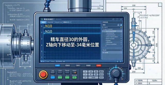
Precision turn a 30 diameter external circle so that the Z-axis moves towards the bottom at the N10 programme segment, all the way to the minus 34 mm position.
N11 X46 (finish turn end face at Z34, move to position X46)
Execute the N12 instruction, the G02 code, the amount of movement of U8, the amount of movement of W4, and the radius value of R4 to perform the fine-turning R4 arc operation, and in the clockwise direction.
N13, G01 instruction with a Z value of minus twenty is used to move down the Z-axis to minus twenty millimetres when finishing a five-four diameter external circle.
To finish turn a tapered surface, the depth of cut is set, as well as the feed speed, where N14, U20, and W10 are also in the relevant work range.
N15 Z3 (finish turning of Φ74 external circle, finish machining of contour)
With the N16 instruction, in the G00 mode, the X-axis goes to the 100 position, the Z-axis goes to the 80 position, and the machining is completed by quickly returning to the tool setting point position.
N17 M30 (spindle stop, main programme execution completed and reset)
![图片[19]-众多编程实例,助你轻松搞定数控车手工编程!-大连富泓机械有限公司](/wp-content/uploads/2026/04/1776774100728_18.png)
![图片[20]-众多编程实例,助你轻松搞定数控车手工编程!-大连富泓机械有限公司](/wp-content/uploads/2026/04/1776774100728_19.png)
![图片[21]-众多编程实例,助你轻松搞定数控车手工编程!-大连富泓机械有限公司](/wp-content/uploads/2026/04/1776774100728_20.png)
![图片[22]-众多编程实例,助你轻松搞定数控车手工编程!-大连富泓机械有限公司](/wp-content/uploads/2026/04/1776774100728_21.png)
![图片[23]-众多编程实例,助你轻松搞定数控车手工编程!-大连富泓机械有限公司](/wp-content/uploads/2026/04/1776774100728_22.png)
![图片[24]-众多编程实例,助你轻松搞定数控车手工编程!-大连富泓机械有限公司](/wp-content/uploads/2026/04/1776774100728_23.png)
![图片[25]-众多编程实例,助你轻松搞定数控车手工编程!-大连富泓机械有限公司](/wp-content/uploads/2026/04/1776774100728_24.png)
![图片[26]-众多编程实例,助你轻松搞定数控车手工编程!-大连富泓机械有限公司](/wp-content/uploads/2026/04/1776774100728_25.png)
Rough machining of φ60mm diameter and φ22mm outer circle with 0.5mm machining allowance. The tools to be used include the roughing cylindrical offset cutter, T01, and the grooving cutter, T02, with a width of 2 mm. The machining procedure is as follows: first, machine the end face of φ22, then rough the outer circle of φ60 mm with a margin of 0.5 mm, then rough the outer circle of φ22 mm with a margin of 0.5 mm, and finally cut off the workpiece, ensuring that the length is 105.5 mm. For details of the machining procedure, please refer to Table 7-10.
Then, the roughly machined φ22mm outer circle is clamped and the φ25mm outer circle is roughly machined by reversing the direction. The tools used for this process include a roughing tool (T01) and a finishing tool (T03). The machining process is as follows: firstly, the endface of φ25mm is machined, then the outer circle of φ25 is roughly machined with a margin of 0.08mm, and finally, the outer circle of φ25mm is finish machined. The specific machining procedure can be viewed in Table 7-11.
After that, the φ25mm outer circle is clamped with a copper pad for alignment, and then the φ22mm outer circle is finish machined. The tool used is the precision cylindrical machining positive offset tool (T03). The machining steps are as follows: first, the φ22mm outer circle is finished, and then the φ60mm outer circle is finished. For details of the machining procedures, please refer to Tables 7-12.
![图片[27]-众多编程实例,助你轻松搞定数控车手工编程!-大连富泓机械有限公司](/wp-content/uploads/2026/04/1776774100728_26.png)
![图片[28]-众多编程实例,助你轻松搞定数控车手工编程!-大连富泓机械有限公司](/wp-content/uploads/2026/04/1776774100728_27.png)
![图片[29]-众多编程实例,助你轻松搞定数控车手工编程!-大连富泓机械有限公司](/wp-content/uploads/2026/04/1776774100728_28.png)
![图片[30]-众多编程实例,助你轻松搞定数控车手工编程!-大连富泓机械有限公司](/wp-content/uploads/2026/04/1776774100728_29.png)
![图片[31]-众多编程实例,助你轻松搞定数控车手工编程!-大连富泓机械有限公司](/wp-content/uploads/2026/04/1776774100728_30.png)
![图片[32]-众多编程实例,助你轻松搞定数控车手工编程!-大连富泓机械有限公司](/wp-content/uploads/2026/04/1776774100728_31.png)
The φ50mm outer circle is clamped, and the work of alignment is carried out. After that, rough machining of φ34mm outer circle, machining of φ42mm outer circle, and cutting of 2×0.5 groove are carried out successively. In this process, a tool with a positive offset (T01) for external machining and a tool with a width of 2 mm (T02) for grooving are used.
Rough machining is carried out on the outer circle of φ42mm with a margin, followed by rough machining of the outer circle of φ34mm with a margin, then finishing machining of the outer circle of φ42mm, followed by grooving, and finally cutting off the workpiece, and the related machining procedures are shown in detail in Tables 7-15.
After performing the above steps, the soft jaws are used to clamp the outer circle with a diameter of φ34mm, and the inner hole is machined. The tools used include a 45° face cutter, numbered (T01), a bore turning tool, numbered (T02), and a grooving tool, numbered (T03), with a width of 4mm. The machining process is as follows: firstly, the end face is machined, then the bore of φ22mm in diameter is roughly machined, then the bore of φ22mm in diameter is finely machined, and finally the grooving is carried out, and the size of the grooving is φ24×16. The specific machining procedure can be seen in Table 7-16.
Next, the workpiece is set onto the mandrel and clamped with two centres, then the outer circle with a diameter of φ34mm is finish-turned, and the tool used is the finishing tool T01, and the machining step is only to finish the outer circle of φ34mm, and the specific machining procedure can be viewed in Table 7-17.
![图片[33]-众多编程实例,助你轻松搞定数控车手工编程!-大连富泓机械有限公司](/wp-content/uploads/2026/04/1776774100728_32.png)
![图片[34]-众多编程实例,助你轻松搞定数控车手工编程!-大连富泓机械有限公司](/wp-content/uploads/2026/04/1776774100728_33.png)
![图片[35]-众多编程实例,助你轻松搞定数控车手工编程!-大连富泓机械有限公司](/wp-content/uploads/2026/04/1776774100728_34.png)
![图片[36]-众多编程实例,助你轻松搞定数控车手工编程!-大连富泓机械有限公司](/wp-content/uploads/2026/04/1776774100728_35.png)
![图片[37]-众多编程实例,助你轻松搞定数控车手工编程!-大连富泓机械有限公司](/wp-content/uploads/2026/04/1776774100728_36.png)
![图片[38]-众多编程实例,助你轻松搞定数控车手工编程!-大连富泓机械有限公司](/wp-content/uploads/2026/04/1776774100728_37.png)
![图片[39]-众多编程实例,助你轻松搞定数控车手工编程!-大连富泓机械有限公司](/wp-content/uploads/2026/04/1776774100728_38.png)
![图片[40]-众多编程实例,助你轻松搞定数控车手工编程!-大连富泓机械有限公司](/wp-content/uploads/2026/04/1776774100728_39.png)
2. Selection of suitable machine tools
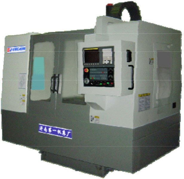
Selection of the economic type in accordance with the requirements set out in the part drawing.CNC latheWe were able to achieve the machining requirements, and in this way, we selected a CNC horizontal lathe.
3. Tool selection
Depending on the machining requirements and to ensure that there is no interference between the tool and the workpiece during machining, a pointed external turning tool or an indexable machine chucked external turning tool is selected to perform roughing and finishing operations.
4. Determine the cutting amount
As for the specific values related to the cutting amount, you have to correlate the performance of the machine tool with the relevant manuals, coupled with practical experience, so that a comprehensive judgement, the specific details, go to see the machining programme.
5. Determine the workpiece co-ordinate system, tool setting points and tool change points.
We take the intersection point O of the right end face of the workpiece and the axis line as the origin of the workpiece, based on which the XOZ workpiece coordinate system is constructed, as shown in Figure 2-20. In the manual tool setting process, we set the intersection point A of the right end face of the workpiece and the cylindrical face of the blank as the tool setting point, again as shown in Figure 2-20. Immediately after this, we will use the MDI method to control the machine and follow these specific steps:
1) Back to reference point operation
By means of ZERO (Return to Reference Point), we carry out the operation of returning to the reference point and thus construct the machine coordinate system.
2)Test cut against the knife
Let the spindle carry out the positive rotation operation, put the tip of the selected lathe tool close to the right end face of the workpiece, then press the button for setting the programming zero point, at this time, the X, Z coordinate value displayed on the CRT screen will be cleared to zero, that is, it will display X0, Z0, then carry out the retracting tool, and make a cut on the outer surface of the workpiece to keep the X dimension unchanged, and carry out the retracting tool in the Z direction at the same time, when the Z coordinate value displayed on the CRT is zero, press the button for setting the programming zero point again, the CRT screen will again display the X, Z coordinate value cleared to zero, that is, X0, Z0. When the Z coordinate value displayed on the CRT is zero, press the button to set the programming zero point again, the CRT screen will again display the X, Z coordinate value is zero, that is, X0, Z0. In this way, the system reaches the programming zero point setting, that is to say, the tool setting point A is set as the programming zero point, which builds up the XAZ′ workpiece coordinate system. Finally, the rotation of the spindle is stopped, and the outer diameter D of the workpiece is measured, and if D is measured, it is φ55㎜.
3)Establish workpiece coordinate system
After the tool setting operation is completed, it is clear that the tip of the tool (the corresponding point of the turning tool) is now located where the zero point of the programming is located, which is the point A of the tool setting. In view of the ease of programming, we have chosen the intersection point O between the right end face of the workpiece and the axis as the origin of the workpiece, and based on this, we have constructed the XOZ workpiece coordinate system. Through the execution of the programme G92 X27.5 Z0, the CNC system will immediately update the display on the CRT screen to show the current position of the tool tip in the XOZ workpiece coordinate system, that is, the X coordinate value is 27.5, Y coordinate value is 0. This shows that the CNC system has already replaced the original XAZ′ workpiece coordinate system with the use of the newly established XOZ workpiece coordinate system.
The tool change point is set in the XOZ workpiece coordinate system, which is at position X15 and also at position Z150.
6. Programming
We in accordance with the instruction code of the lathe and the format of the programme segment, the processing of the part of a whole process has been painstakingly written into a programme list for the workpiece, its machining procedures are as follows, it is important to note that this system in the X direction is used in the radius of the programming method Oh:
![图片[41]-众多编程实例,助你轻松搞定数控车手工编程!-大连富泓机械有限公司](/wp-content/uploads/2026/04/1776774100728_40.png)
![图片[42]-众多编程实例,助你轻松搞定数控车手工编程!-大连富泓机械有限公司](/wp-content/uploads/2026/04/1776774100728_41.png)
![图片[43]-众多编程实例,助你轻松搞定数控车手工编程!-大连富泓机械有限公司](/wp-content/uploads/2026/04/1776774100728_42.png)
![图片[44]-众多编程实例,助你轻松搞定数控车手工编程!-大连富泓机械有限公司](/wp-content/uploads/2026/04/1776774100728_43.png)
![图片[45]-众多编程实例,助你轻松搞定数控车手工编程!-大连富泓机械有限公司](/wp-content/uploads/2026/04/1776774100728_44.png)
![图片[46]-众多编程实例,助你轻松搞定数控车手工编程!-大连富泓机械有限公司](/wp-content/uploads/2026/04/1776774100728_45.png)
As of this moment, we have given you 30 examples that have been carefully selected, and we pray that these examples will bring you some help.


No comments